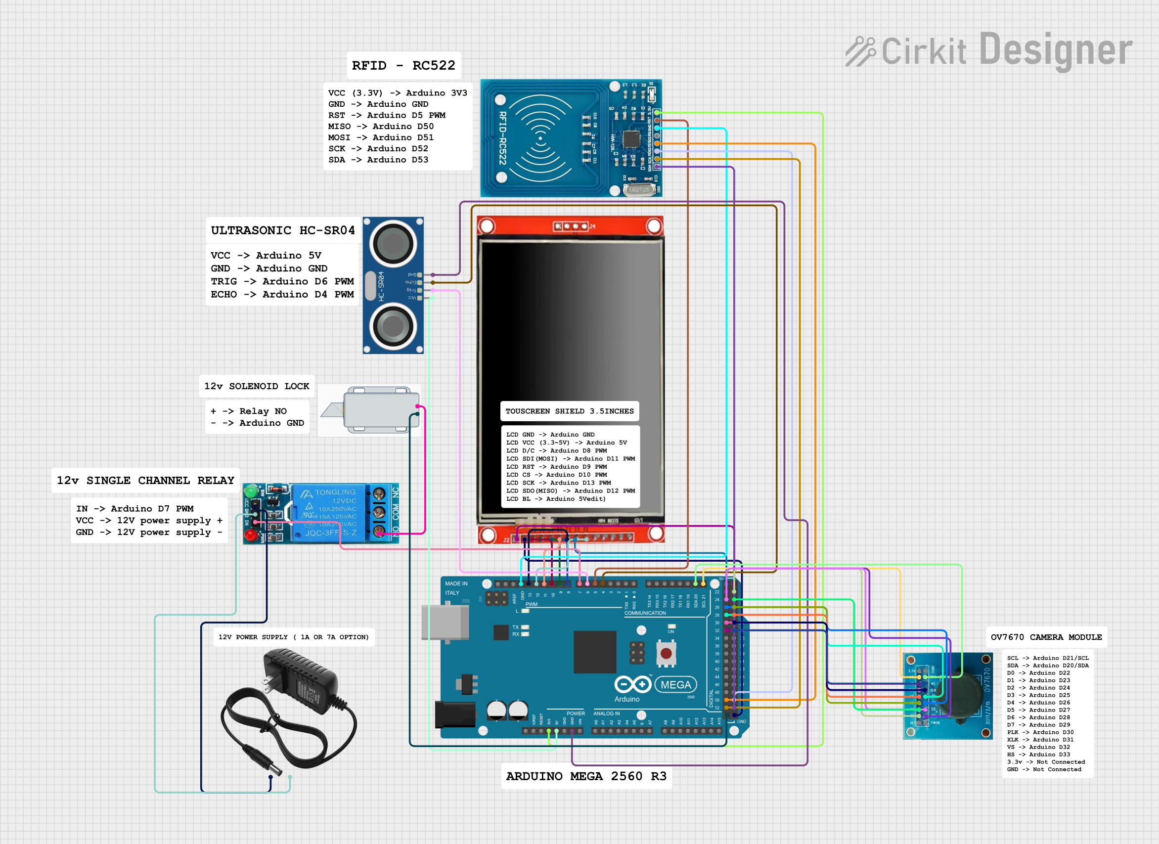
Arduino Mega 2560-Based Access Control System with RFID, Ultrasonic Sensing, and Visual Feedback

Circuit Documentation
Summary
This document provides a detailed overview of a circuit designed to interface various components with an Arduino Mega 2560 microcontroller. The circuit includes an RFID-RC522 module for RFID reading, an HC-SR04 Ultrasonic Sensor for distance measurement, an OV7670 camera module for image capture, a 12V Solenoid Lock for locking mechanisms, a 12V Single Channel Relay for controlling high power devices, and an LCD TFT screen ILI9488 HD for display purposes. The circuit is powered by a 12V power supply, and the Arduino Mega 2560 serves as the central processing unit, controlling the interactions between the components.
Component List
- Arduino Mega 2560: A microcontroller board based on the ATmega2560, with numerous digital and analog I/O pins.
- 12V Solenoid Lock: An electromagnetic lock that operates at 12V.
- RFID-RC522: An RFID reader/writer module.
- HC-SR04 Ultrasonic Sensor: A sensor for measuring distance via ultrasonic waves.
- 12V Single Channel Relay: A relay module for controlling high voltage/current devices.
- OV7670: A camera module capable of capturing images.
- LCD TFT screen ILI9488 HD: A high-definition LCD screen for display purposes.
- 12V Power Supply: A power source for the circuit, providing 12V.
Wiring Details
Arduino Mega 2560
3V3connected to RFID-RC522 VCC (3.3V)5Vconnected to HC-SR04 Ultrasonic Sensor VCC and LCD TFT screen ILI9488 HD VCC (3.3~5V)GNDconnected to HC-SR04 Ultrasonic Sensor GND, RFID-RC522 GND, OV7670 DGND, and LCD TFT screen ILI9488 HD GNDD21/SCLconnected to OV7670 SCLD20/SDAconnected to OV7670 SDAD4 PWMconnected to HC-SR04 Ultrasonic Sensor ECHOD5 PWMconnected to RFID-RC522 RSTD6 PWMconnected to HC-SR04 Ultrasonic Sensor TRIGD7 PWMconnected to 12V Single Channel Relay IND8 PWMconnected to LCD TFT screen ILI9488 HD D/CD9 PWMconnected to LCD TFT screen ILI9488 HD RSTD10 PWMconnected to LCD TFT screen ILI9488 HD CSD11 PWMconnected to LCD TFT screen ILI9488 HD SDI(MOSI)D12 PWMconnected to LCD TFT screen ILI9488 HD SDO(MISO)D13 PWMconnected to LCD TFT screen ILI9488 HD SCKD52connected to RFID-RC522 SCKD50connected to RFID-RC522 MISOD53connected to RFID-RC522 SDAD51connected to RFID-RC522 MOSID32connected to OV7670 VSD30connected to OV7670 PLKD28connected to OV7670 D6D26connected to OV7670 D4D24connected to OV7670 D2D22connected to OV7670 D0D33connected to OV7670 HSD31connected to OV7670 XLKD29connected to OV7670 D7D27connected to OV7670 D5D25connected to OV7670 D3D23connected to OV7670 D1
12V Solenoid Lock
-connected to Arduino Mega 2560 GND+connected to 12V Single Channel Relay NO
RFID-RC522
VCC (3.3V)connected to Arduino Mega 2560 3V3RSTconnected to Arduino Mega 2560 D5 PWMGNDconnected to Arduino Mega 2560 GNDSCKconnected to Arduino Mega 2560 D52MISOconnected to Arduino Mega 2560 D50MOSIconnected to Arduino Mega 2560 D51SDAconnected to Arduino Mega 2560 D53
HC-SR04 Ultrasonic Sensor
VCCconnected to Arduino Mega 2560 5VTRIGconnected to Arduino Mega 2560 D6 PWMECHOconnected to Arduino Mega 2560 D4 PWMGNDconnected to Arduino Mega 2560 GND
12V Single Channel Relay
INconnected to Arduino Mega 2560 D7 PWMVCCconnected to 12V Power Supply +GNDconnected to 12V Power Supply -NOconnected to 12V Solenoid Lock +
OV7670
SCLconnected to Arduino Mega 2560 D21/SCLSDAconnected to Arduino Mega 2560 D20/SDAVSconnected to Arduino Mega 2560 D32PLKconnected to Arduino Mega 2560 D30D6connected to Arduino Mega 2560 D28D4connected to Arduino Mega 2560 D26D2connected to Arduino Mega 2560 D24D0connected to Arduino Mega 2560 D22HSconnected to Arduino Mega 2560 D33XLKconnected to Arduino Mega 2560 D31D7connected to Arduino Mega 2560 D29D5connected to Arduino Mega 2560 D27D3connected to Arduino Mega 2560 D25D1connected to Arduino Mega 2560 D23
LCD TFT screen ILI9488 HD
D/Cconnected to Arduino Mega 2560 D8 PWMRSTconnected to Arduino Mega 2560 D9 PWMCSconnected to Arduino Mega 2560 D10 PWMSDI(MOSI)connected to Arduino Mega 2560 D11 PWMSDO(MISO)connected to Arduino Mega 2560 D12 PWMSCKconnected to Arduino Mega 2560 D13 PWMBLconnected to Arduino Mega 2560 5VGNDconnected to Arduino Mega 2560 GNDVCC (3.3~5V)connected to Arduino Mega 2560 5V
Documented Code
Arduino Mega 2560
File: sketch.ino
void setup() {
  // put your setup code here, to run once:

}

void loop() {
  // put your main code here, to run repeatedly:

}
File: documentation.txt
(No additional documentation provided for the code)
This concludes the documentation for the circuit. The wiring details provide a clear guide for connecting the components, and the code section provides a template for further development of the firmware to control the circuit's functionality.