
ESP32-Based Battery-Powered RFID Reader with OLED Display and Distance Sensor
View and Edit Project In Cirkit Designer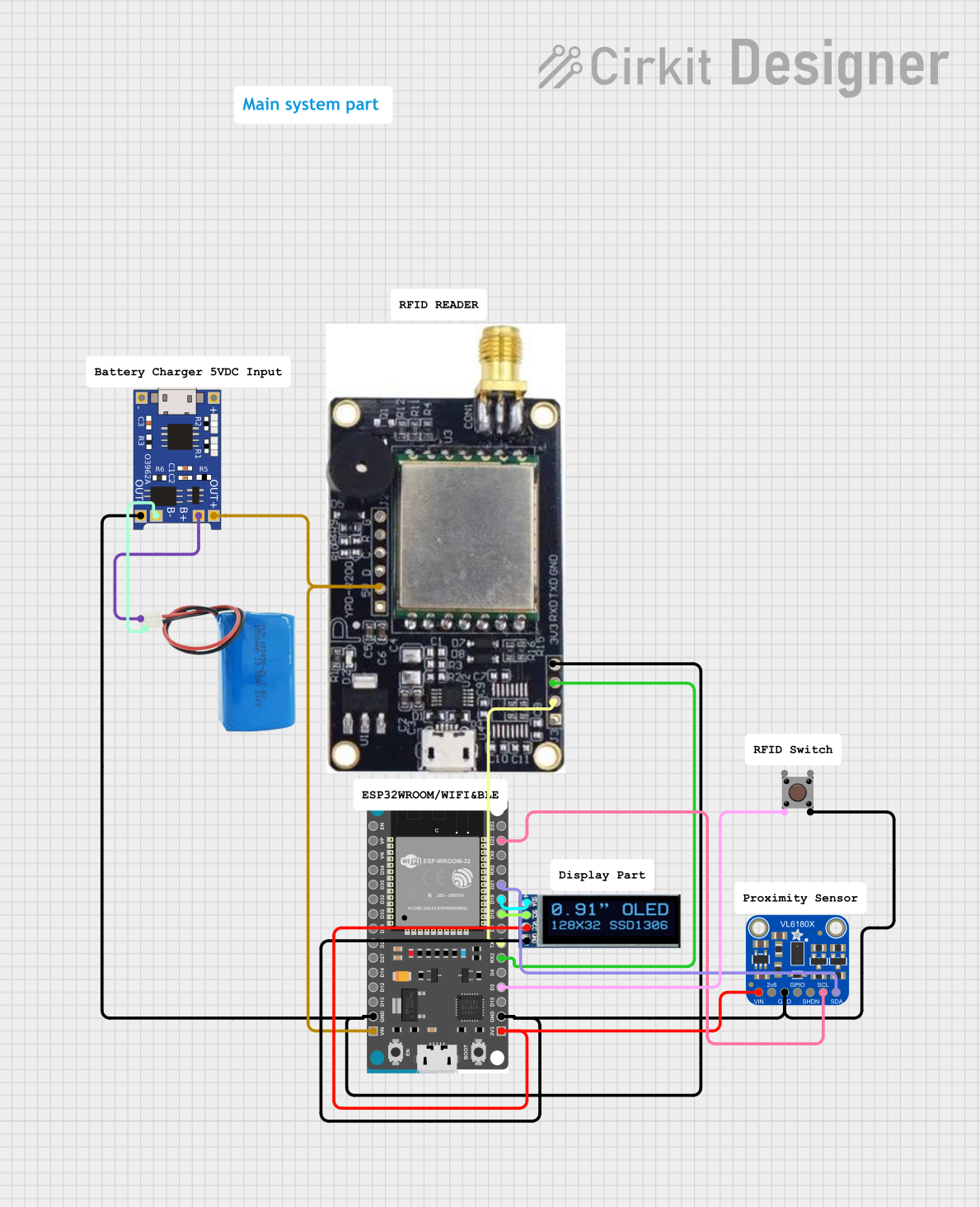
Circuit Documentation
Summary
This circuit involves an ESP32 microcontroller connected to a UHF RFID module, an Adafruit VL6180X Time of Flight Distance Sensor, an OLED display, and a pushbutton. The ESP32 communicates with the RFID module via UART, reads distance data from the VL6180X sensor via I2C, and displays the distance on the OLED display. Additionally, it reads the state of the pushbutton and prints it to the serial monitor. The circuit is powered by a 5V battery managed by a TP4056 module.
Component List
ESP32 Devkit V1
- Description: Microcontroller with Wi-Fi and Bluetooth capabilities.
- Pins: 3V3, GND, D15, D2, D4, RX2, TX2, D5, D18, D19, D21, RX0, TX0, D22, D23, EN, VP, VN, D34, D35, D32, D33, D25, D26, D27, D14, D12, D13, VIN
UHF RFID IN-R200
- Description: UHF RFID module for reading RFID tags.
- Pins: 3.3v, RXD, TXD, GND, 5v, D, C, R, G
Adafruit VL6180X Time of Flight Distance Sensor
- Description: Sensor for measuring distance using time of flight.
- Pins: VIN, 2.8V, GND, GPIO, XSHUT, SCL, SDA
oled_display_128_32
- Description: 128x32 pixel OLED display.
- Pins: SDA, SCL, VCC, GND
Pushbutton
- Description: Simple pushbutton for user input.
- Pins: Pin 3 (out), Pin 4 (out), Pin 1 (in), Pin 2 (in)
5v battery
- Description: Power source for the circuit.
- Pins: positive, negative
TP4056
- Description: Lithium battery charger module.
- Pins: OUT-, B-, B+, OUT+, IN-, IN+
Wiring Details
ESP32 Devkit V1
- TX2 connected to RXD of UHF RFID IN-R200
- RX2 connected to TXD of UHF RFID IN-R200
- GND connected to GND of UHF RFID IN-R200, OUT- of TP4056, GND of oled_display_128_32, GND of Adafruit VL6180X Time of Flight Distance Sensor, and Pin 4 (out) of Pushbutton
- VIN connected to 5v of UHF RFID IN-R200 and OUT+ of TP4056
- 3V3 connected to VCC of oled_display_128_32 and VIN of Adafruit VL6180X Time of Flight Distance Sensor
- D2 connected to Pin 2 (in) of Pushbutton
- D18 connected to SCL of oled_display_128_32
- D19 connected to SDA of oled_display_128_32
- D21 connected to SDA of Adafruit VL6180X Time of Flight Distance Sensor
- D22 connected to SCL of Adafruit VL6180X Time of Flight Distance Sensor
UHF RFID IN-R200
- RXD connected to TX2 of ESP32 Devkit V1
- TXD connected to RX2 of ESP32 Devkit V1
- GND connected to GND of ESP32 Devkit V1
- 5v connected to VIN of ESP32 Devkit V1
Adafruit VL6180X Time of Flight Distance Sensor
- VIN connected to 3V3 of ESP32 Devkit V1
- GND connected to GND of ESP32 Devkit V1
- SCL connected to D22 of ESP32 Devkit V1
- SDA connected to D21 of ESP32 Devkit V1
oled_display_128_32
- VCC connected to 3V3 of ESP32 Devkit V1
- GND connected to GND of ESP32 Devkit V1
- SCL connected to D18 of ESP32 Devkit V1
- SDA connected to D19 of ESP32 Devkit V1
Pushbutton
- Pin 4 (out) connected to GND of ESP32 Devkit V1
- Pin 2 (in) connected to D2 of ESP32 Devkit V1
5v battery
- negative connected to B- of TP4056
- positive connected to B+ of TP4056
TP4056
- OUT- connected to GND of ESP32 Devkit V1
- OUT+ connected to VIN of ESP32 Devkit V1
- B- connected to negative of 5v battery
- B+ connected to positive of 5v battery
Code Documentation
/*
 * Test6
 * This Arduino Sketch is for an ESP32 microcontroller connected to a UHF RFID
 * module, an Adafruit VL6180X Time of Flight Distance Sensor, an OLED display,
 * and a pushbutton. The code initializes UART communication with the RFID
 * module, reads distance data from the VL6180X sensor, and displays the
 * distance on the OLED display. Additionally, it reads the state of the
 * pushbutton and prints it to the serial monitor.
 */

#include <Wire.h>
#include <Adafruit_VL6180X.h>
#include <Adafruit_SSD1306.h>

#define SCREEN_WIDTH 128
#define SCREEN_HEIGHT 32
#define OLED_RESET -1
Adafruit_SSD1306 display(SCREEN_WIDTH, SCREEN_HEIGHT, &Wire, OLED_RESET);

#define RFID_RX_PIN 16 // RX2 on ESP32
#define RFID_TX_PIN 17 // TX2 on ESP32
#define VL6180X_SCL_PIN 22
#define VL6180X_SDA_PIN 21
#define OLED_SCL_PIN 18
#define OLED_SDA_PIN 19
#define BUTTON_PIN 2

Adafruit_VL6180X vl = Adafruit_VL6180X();

void setup() {
  // Initialize serial communication for debugging
  Serial.begin(115200);
  // Initialize UART communication with RFID module
  Serial2.begin(9600, SERIAL_8N1, RFID_RX_PIN, RFID_TX_PIN);
  // Initialize I2C communication for VL6180X sensor
  Wire.begin(VL6180X_SDA_PIN, VL6180X_SCL_PIN);
  if (!vl.begin()) {
    Serial.println("Failed to find VL6180X sensor");
    while (1);
  }
  // Initialize OLED display
  if (!display.begin(SSD1306_SWITCHCAPVCC, 0x3C)) {
    Serial.println("SSD1306 allocation failed");
    while (1);
  }
  display.display();
  delay(2000);
  display.clearDisplay();
  display.setTextSize(1);
  display.setTextColor(SSD1306_WHITE);
  // Initialize pushbutton pin
  pinMode(BUTTON_PIN, INPUT);
  // Print setup complete message
  Serial.println("Setup complete");
}

void loop() {
  // Read data from RFID module
  if (Serial2.available()) {
    String rfidData = Serial2.readString();
    Serial.println("RFID Data: " + rfidData);
  }
  // Read distance data from VL6180X sensor
  uint8_t range = vl.readRange();
  uint8_t status = vl.readRangeStatus();
  if (status == VL6180X_ERROR_NONE) {
    Serial.print("Distance: ");
    Serial.print(range);
    Serial.println(" mm");
    display.clearDisplay();
    display.setCursor(0, 0);
    display.print("Distance: ");
    display.print(range);
    display.print(" mm");
    display.display();
  } else {
    Serial.println("Error reading distance");
  }
  // Read pushbutton state
  int buttonState = digitalRead(BUTTON_PIN);
  Serial.print("Button State: ");
  Serial.println(buttonState);
}
This code initializes the necessary peripherals and continuously reads data from the RFID module, distance sensor, and pushbutton, displaying the results on the OLED display and serial monitor.