Cirkit Designer
Your all-in-one circuit design IDE
Home /
Project Documentation
ESP32-CAM and Arduino UNO Controlled Robotics Platform with Servo and DC Motors
Circuit Documentation
Summary
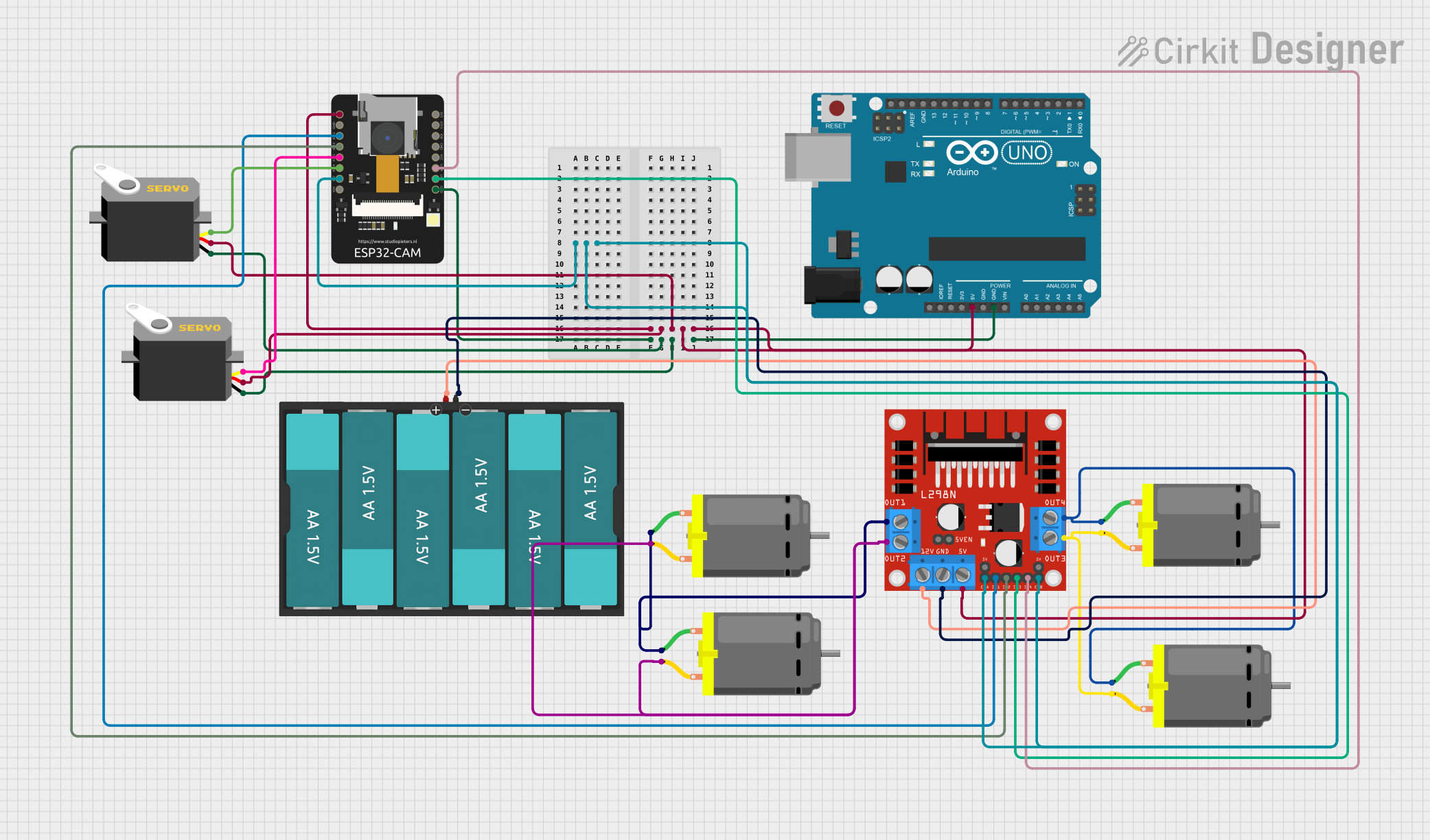
This circuit integrates a variety of components including microcontrollers, motor drivers, servos, DC motors, and a power source. The primary microcontroller is an Arduino UNO, which is intended to interface with an ESP32-CAM module. The ESP32-CAM provides camera functionality and additional GPIO for control signals. The L298N DC motor driver is used to control multiple DC motors, and servos are included for precise angular movement. The entire circuit is powered by a 9V battery pack consisting of six AA batteries.
Component List
Arduino UNO
- Microcontroller board based on the ATmega328P
- It has 14 digital input/output pins, 6 analog inputs, a 16 MHz quartz crystal, a USB connection, a power jack, an ICSP header, and a reset button.
ESP32 - CAM
- A small-sized camera module featuring an ESP32-S chip that besides offering Wi-Fi and Bluetooth also provides camera interface capabilities.
L298N DC Motor Driver
- A dual H-bridge motor driver capable of driving a pair of DC motors or a single stepper motor.
- It has 4 input pins for controlling the direction and speed of the motors and 4 output pins for motor connections.
DC Motor
- A simple electric motor that converts electrical energy into mechanical energy.
- It has two pins for power connection, which determine the rotation direction based on polarity.
Servo
- An actuator that enables precise control of angular position, velocity, and acceleration.
- It has three pins: power (VCC), ground (GND), and control (pulse).
Battery AAx6 9V
- A battery pack consisting of six AA batteries to provide a 9V power supply.
Wiring Details
Arduino UNO
- 5V: Connected to the 5V power rail supplying power to the ESP32-CAM, servos, and L298N motor driver.
- GND: Connected to the ground rail, which is common for all components.
ESP32 - CAM
- 5V: Receives power from the 5V rail.
- GND: Connected to the ground rail.
- IO12, IO13, IO2, VOT, VOR: Control signals connected to the L298N motor driver for motor control.
- IO15, IO14: Control signals connected to the servos for pulse control.
L298N DC Motor Driver
- 5V: Receives power from the 5V rail.
- 12V: Receives power from the 9V battery pack.
- GND: Connected to the ground rail.
- IN1, IN2, IN3, IN4: Control inputs from the ESP32-CAM for motor direction and speed control.
- ENA, ENB: Enable pins for motor control, connected to IO2 of the ESP32-CAM.
- OUT1, OUT2, OUT3, OUT4: Outputs connected to the DC motors.
DC Motors
- Pin 1 and Pin 2: Connected to the outputs of the L298N motor driver. The polarity determines the direction of rotation.
Servos
- VCC: Receives power from the 5V rail.
- GND: Connected to the ground rail.
- Pulse: Receives control signals from the ESP32-CAM for position control.
Battery AAx6 9V
- VCC: Provides power to the L298N motor driver.
- GND: Connected to the ground rail.
Documented Code
Arduino UNO - sketch.ino
void setup() {
  // put your setup code here, to run once:

}

void loop() {
  // put your main code here, to run repeatedly:

}
Note: The provided code for the Arduino UNO is a template with empty setup and loop functions. The user is expected to fill in the code according to the specific requirements of the circuit.
Additional Files
- documentation.txt: This file is mentioned but no content is provided. It is likely intended for additional notes or manual documentation.