
Circuit Documentation
Summary of the Circuit
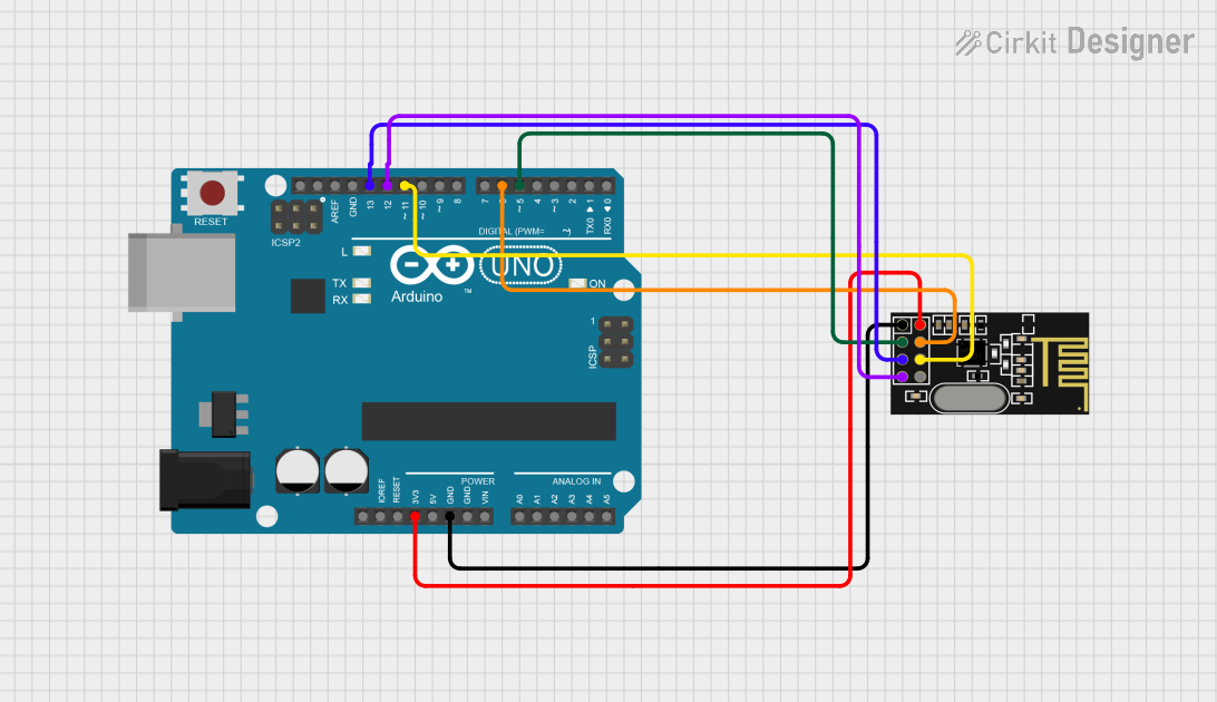
This circuit integrates an Arduino UNO microcontroller board with an NRF24L01 wireless transceiver module. The purpose of this setup is to enable wireless communication capabilities for the Arduino UNO, allowing it to send and receive data wirelessly via the NRF24L01 module. The connections between the Arduino UNO and the NRF24L01 include power supply lines, ground, and SPI communication lines.
Component List
Arduino UNO
- Description: A microcontroller board based on the ATmega328P. It has 14 digital input/output pins, 6 analog inputs, a 16 MHz quartz crystal, a USB connection, a power jack, an ICSP header, and a reset button.
- Purpose in Circuit: Acts as the main controller and interfaces with the NRF24L01 module for wireless communication.
NRF24L01
- Description: A 2.4GHz wireless transceiver module with an SPI interface.
- Purpose in Circuit: Provides wireless communication capabilities to the Arduino UNO.
Wiring Details
Arduino UNO
- 3.3V - Provides power to the NRF24L01 module.
- GND - Common ground with the NRF24L01 module.
- D13 (SCK) - Serial Clock line for SPI communication with the NRF24L01 module.
- D12 (MISO) - Master In Slave Out line for SPI communication with the NRF24L01 module.
- D11 (MOSI) - Master Out Slave In line for SPI communication with the NRF24L01 module.
- D6 (CSN) - Chip Select Not line for SPI communication with the NRF24L01 module.
- D5 (CE) - Chip Enable line for the NRF24L01 module.
NRF24L01
- VCC (3V) - Powered by the 3.3V output from the Arduino UNO.
- GND - Common ground with the Arduino UNO.
- SCK - Serial Clock line connected to D13 on the Arduino UNO.
- MISO - Master In Slave Out line connected to D12 on the Arduino UNO.
- MOSI - Master Out Slave In line connected to D11 on the Arduino UNO.
- CSN - Chip Select Not line connected to D6 on the Arduino UNO.
- CE - Chip Enable line connected to D5 on the Arduino UNO.
Documented Code
Arduino UNO Code (sketch.ino)
void setup() {
  // put your setup code here, to run once:

}

void loop() {
  // put your main code here, to run repeatedly:

}
The provided code is a template with empty setup() and loop() functions, which are the entry points for Arduino sketches. The setup() function is called once when the sketch starts and is used for initializing settings or pin modes. The loop() function is called repeatedly and contains the main logic of the sketch.
For this circuit, the code would need to initialize the SPI interface and configure the necessary pins for communication with the NRF24L01 module. The main loop would handle the sending and receiving of data wirelessly. However, the specific implementation details are not provided in the given code snippet.