
Arduino UNO R4 WiFi Joystick-Controlled LED Matrix with Wi-Fi Connectivity
View and Edit Project In Cirkit Designer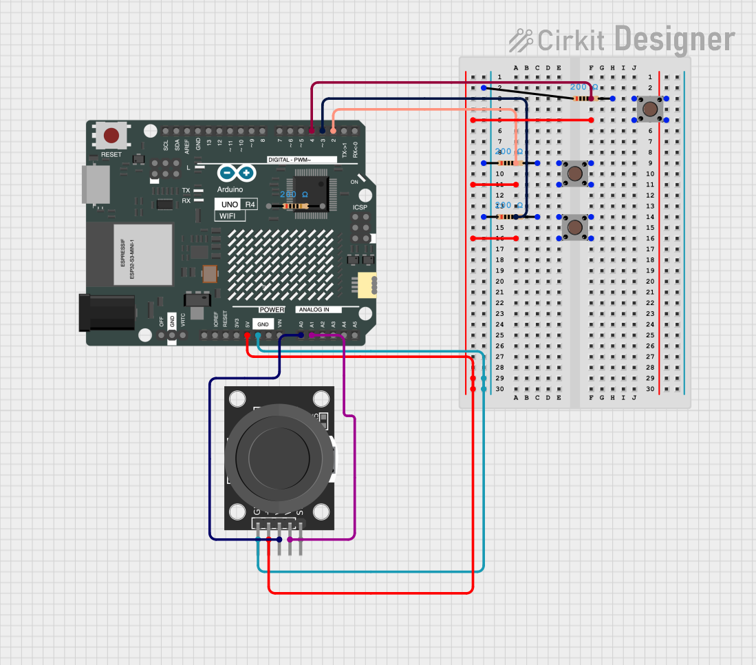
Circuit Documentation
Summary
This circuit consists of an Arduino UNO R4 WiFi microcontroller, a KY-023 Dual Axis Joystick Module, three pushbuttons, and four resistors. The circuit is designed to read inputs from the joystick and pushbuttons, process the data using the Arduino, and send the data over WiFi to a specified host. The Arduino also controls an LED matrix to display animations.
Component List
Arduino UNO R4 WiFi
- Description: A microcontroller board based on the ATmega328P, featuring built-in WiFi capabilities.
- Pins: OFF, GND, VRTC, IIC0_SCL, IIC0_SDA, 3V3, GPIO 41, GPIO 0, GPIO 42, GPIO 43, GPIO 44, BOOT, IOREF, RESET, 5V, VIN, A0, A1, A2, A3, A4, A5, RSPCKA, CIPO, COPI, D0/RX, D1/TX, D2, D3, D4, D5, D6, D7, D8, D9, D10, D11, D12, D13, AREF, SDA, SCL
KY-023 Dual Axis Joystick Module
- Description: A joystick module that provides analog output for X and Y axes and a digital output for the switch.
- Pins: GND, +5V, VRx, VRy, SW
Pushbutton
- Description: A simple pushbutton switch.
- Pins: Pin 3 (out), Pin 4 (out), Pin 1 (in), Pin 2 (in)
Resistor
- Description: A resistor with a resistance of 200 Ohms.
- Pins: pin1, pin2
Wiring Details
Arduino UNO R4 WiFi
- 5V: Connected to +5V of the KY-023 Dual Axis Joystick Module and Pin 1 (in) of all pushbuttons.
- GND: Connected to GND of the KY-023 Dual Axis Joystick Module and pin1 of all resistors.
- D2: Connected to pin2 of the resistor and Pin 3 (out) of the second pushbutton.
- D3: Connected to pin2 of the resistor and Pin 3 (out) of the third pushbutton.
- D4: Connected to pin2 of the resistor and Pin 3 (out) of the first pushbutton.
- A0: Connected to VRx of the KY-023 Dual Axis Joystick Module.
- A1: Connected to VRy of the KY-023 Dual Axis Joystick Module.
KY-023 Dual Axis Joystick Module
- GND: Connected to GND of the Arduino UNO R4 WiFi and pin1 of all resistors.
- +5V: Connected to 5V of the Arduino UNO R4 WiFi and Pin 1 (in) of all pushbuttons.
- VRx: Connected to A0 of the Arduino UNO R4 WiFi.
- VRy: Connected to A1 of the Arduino UNO R4 WiFi.
Pushbutton 1
- Pin 1 (in): Connected to 5V of the Arduino UNO R4 WiFi.
- Pin 2 (in): Connected to Pin 4 (out) of the same pushbutton.
- Pin 3 (out): Connected to pin2 of the resistor and D4 of the Arduino UNO R4 WiFi.
- Pin 4 (out): Connected to Pin 2 (in) of the same pushbutton.
Pushbutton 2
- Pin 1 (in): Connected to 5V of the Arduino UNO R4 WiFi.
- Pin 3 (out): Connected to pin2 of the resistor and D2 of the Arduino UNO R4 WiFi.
Pushbutton 3
- Pin 1 (in): Connected to 5V of the Arduino UNO R4 WiFi.
- Pin 3 (out): Connected to pin2 of the resistor and D3 of the Arduino UNO R4 WiFi.
Resistor 1
- pin1: Connected to GND of the Arduino UNO R4 WiFi.
- pin2: Connected to Pin 3 (out) of the first pushbutton and D4 of the Arduino UNO R4 WiFi.
Resistor 2
- pin1: Connected to GND of the Arduino UNO R4 WiFi.
- pin2: Connected to Pin 3 (out) of the second pushbutton and D2 of the Arduino UNO R4 WiFi.
Resistor 3
- pin1: Connected to GND of the Arduino UNO R4 WiFi.
- pin2: Connected to Pin 3 (out) of the third pushbutton and D3 of the Arduino UNO R4 WiFi.
Resistor 4
- pin1: Connected to GND of the Arduino UNO R4 WiFi.
Code Documentation
sketch.ino
#include "Arduino_LED_Matrix.h"
ArduinoLEDMatrix matrix;
#include "animation.h"

#include <WiFi.h>
#include <WiFiUdp.h>

// Replace with your network credentials
const char* ssid = "xxx";
const char* password = "xxx";

// Set the IP address and port of the Python script (receiver)
const char* host = "192.168.1.247";  // Replace with the IP address of the computer running the Python script
const int port = 12345;            // Set a port number

WiFiUDP udp;

//-----------------------------------------------------------------------------------------------------------------
int switchState = 0;
int water = 0;
int switchenter = 0;
#define X_pin A0
#define Y_pin A1

void setup() {
  //------------------------------------------------------------------------------------------------------------------
  Serial.begin(115200);
  matrix.loadSequence(frames);
  matrix.begin();
  matrix.play(true);
  Serial.begin(115200);

  // Connect to WiFi
  WiFi.begin(ssid, password);
  while (WiFi.status() != WL_CONNECTED) {
    delay(1000);
    Serial.print(".");
  }
  Serial.println("");
  Serial.println("Connected to WiFi");

  // Start the UDP communication with a specific port
  udp.begin(port); // Instead of udp.localPort(), we manually specify the port here.
  //------------------------------------------------------------------------------------------------------

  // Initialize joystick and buttons
  pinMode(2, INPUT);
  pinMode(3, INPUT);
  pinMode(4, INPUT);
}

void loop() {
  // Read joystick and button states
  switchState = digitalRead(2);
  water = digitalRead(3);
  switchenter = digitalRead(4);
  int x = analogRead(X_pin) - 512;
  int y = analogRead(Y_pin) - 512;

  // Create the message string
  String message = "S" + String(x) + "," + String(y) + "," + String(switchState) + "," + String(water) + "," + String(switchenter);

  // Convert the message to a C-style string (const char*)
  const char* messageCStr = message.c_str();

  // Send data through WebSocket (or UDP)
  udp.beginPacket(host, port);
  udp.write((const uint8_t*)messageCStr, strlen(messageCStr));  // Cast to uint8_t* and send
  udp.endPacket();

  Serial.println("Message sent");

  delay(50);  // Send every 50 milliseconds
}
animation.h
#include <stdint.h>
const unsigned long frames[][4] = {
  {
    0xe0000000,
    0x0,
    0x0,
    66
  },
  {
    0x400e0000,
    0x0,
    0x0,
    66
  },
  {
    0x400e0,
    0x0,
    0x0,
    66
  },
  {
    0x40,
    0xe000000,
    0x0,
    66
  },
  {
    0x3000000,
    0x400e000,
    0x0,
    66
  },
  {
    0x3003000,
    0x400e,
    0x0,
    66
  },
  {
    0x3003,
    0x4,
    0xe00000,
    66
  },
  {
    0x3,
    0x300000,
    0x400e00,
    66
  },
  {
    0x0,
    0x300300,
    0x400e00,
    66
  },
  {
    0x1c000000,
    0x300,
    0x30400e00,
    66
  },
  {
    0x401c000,
    0x0,
    0x30430e00,
    66
  },
  {
    0x401c,
    0x0,
    0