
Arduino Nano Controlled Multi-Stepper Motor System with Limit Switches and Emergency Stop
View and Edit Project In Cirkit Designer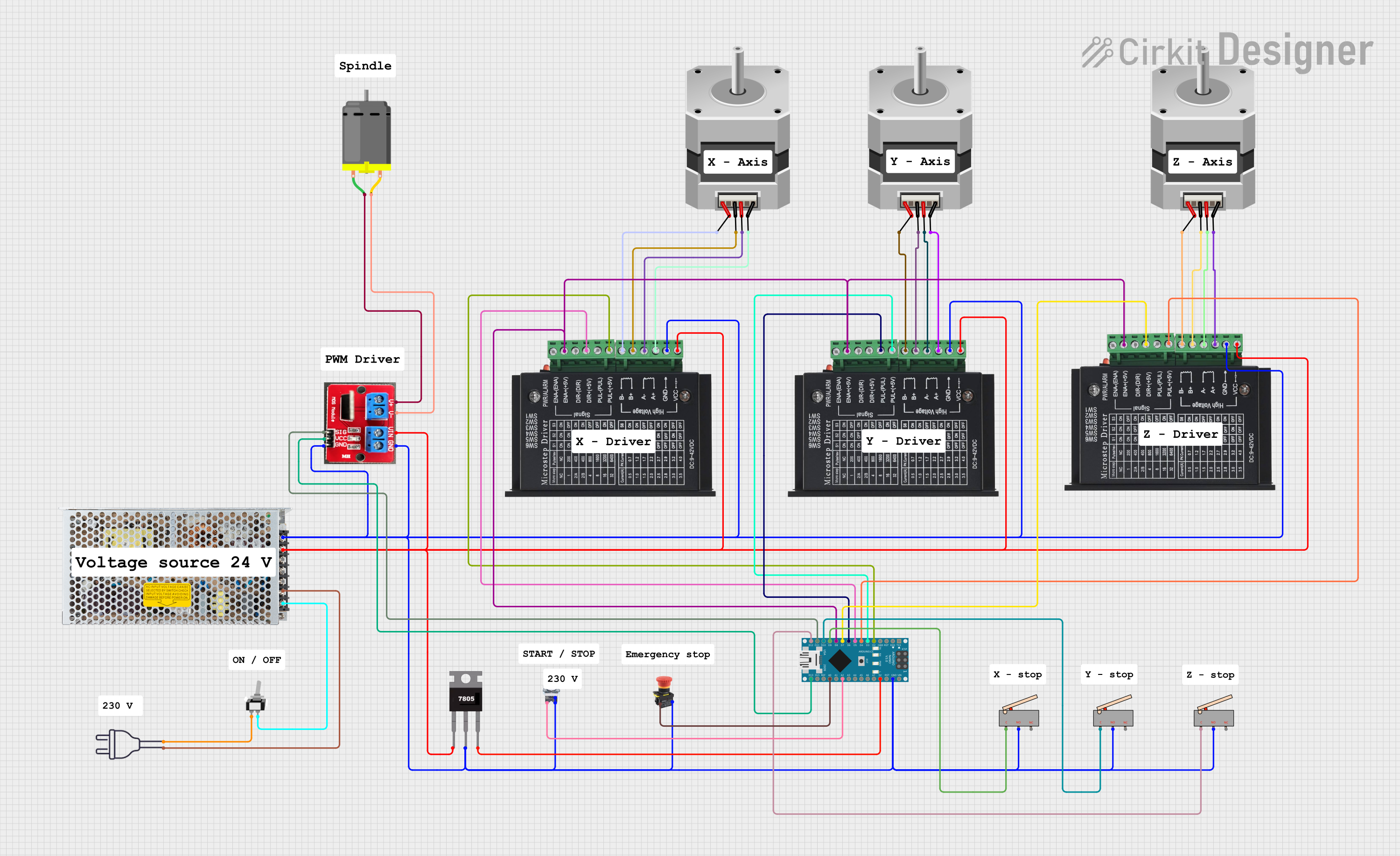
Circuit Documentation
Summary
This circuit is designed to control multiple stepper motors and a DC motor using an Arduino Nano. The circuit includes motor drivers, limit switches, a power supply, and various control buttons. The Arduino Nano is programmed to manage the motor operations and respond to the limit switches and control buttons.
Component List
Arduino Nano
- Description: A small, complete, and breadboard-friendly board based on the ATmega328P.
- Pins: D1/TX, D0/RX, RESET, GND, D2, D3, D4, D5, D6, D7, D8, D9, D10, D11/MOSI, D12/MISO, VIN, 5V, A7, A6, A5, A4, A3, A2, A1, A0, AREF, 3V3, D13/SCK
tb6600 Micro Stepping Motor Driver
- Description: A microstepping driver suitable for driving bipolar stepper motors.
- Pins: ENA-, ENA+, DIR-, DIR+, PUL-, PUL+, B-, B+, A-, A+, GND, VCC
Switching Power Supply
- Description: Provides regulated power to the circuit.
- Pins: AC, GND, -V, +V
Stepper Motor (Bipolar)
- Description: A type of stepper motor that requires a bipolar driver.
- Pins: D, B, C, A
7805
- Description: A voltage regulator that outputs 5V.
- Pins: Vin, Gnd, Vout
Limit switch
- Description: A switch used to detect the presence or absence of an object.
- Pins: C, NO, NC
IRF520 PWM
- Description: A MOSFET module used for PWM control of DC motors.
- Pins: V+, V-, Vin, GND, SIG, Vcc
DC Motor
- Description: A motor that runs on direct current.
- Pins: pin 1, pin 2
Emergency STOP
- Description: A switch used to immediately stop the circuit in case of an emergency.
- Pins: NC
Pushbutton START
- Description: A button used to start the circuit.
- Pins: NC, NO
power 220v
- Description: Provides 220V AC power to the circuit.
- Pins: hot wire, neutral wire
Toggle Switch spst
- Description: A single-pole single-throw switch used to control the power supply.
- Pins: L1, COM
Wiring Details
Arduino Nano
- D8: Connected to ENA+ of all tb6600 Micro Stepping Motor Drivers.
- D5: Connected to DIR+ of tb6600 Micro Stepping Motor Driver.
- D2: Connected to PUL+ of tb6600 Micro Stepping Motor Driver.
- D3: Connected to PUL+ of tb6600 Micro Stepping Motor Driver.
- D4: Connected to PUL+ of tb6600 Micro Stepping Motor Driver.
- D6: Connected to PUL- of tb6600 Micro Stepping Motor Driver.
- D7: Connected to DIR+ of tb6600 Micro Stepping Motor Driver.
- D9: Connected to C of Limit switch.
- D10: Connected to C of Limit switch.
- D11/MOSI: Connected to SIG of IRF520 PWM.
- D12/MISO: Connected to C of Limit switch.
- D13/SCK: Connected to Vcc of IRF520 PWM.
- GND: Connected to GND of tb6600 Micro Stepping Motor Drivers, Limit switches, Switching Power Supply, 7805, Pushbutton START, and IRF520 PWM.
- 5V: Connected to Vout of 7805.
- A2: Connected to NO of Pushbutton START.
- A0: Connected to NC of Emergency STOP.
tb6600 Micro Stepping Motor Driver
- ENA+: Connected to D8 of Arduino Nano.
- DIR+: Connected to D5 of Arduino Nano.
- PUL+: Connected to D2, D3, D4 of Arduino Nano.
- PUL-: Connected to D6 of Arduino Nano.
- DIR+: Connected to D7 of Arduino Nano.
- B-: Connected to A of Stepper Motor (Bipolar).
- B+: Connected to C of Stepper Motor (Bipolar).
- A-: Connected to B of Stepper Motor (Bipolar).
- A+: Connected to D of Stepper Motor (Bipolar).
- GND: Connected to GND of Arduino Nano.
- VCC: Connected to +V of Switching Power Supply.
Switching Power Supply
- AC: Connected to COM of Toggle Switch spst and hot wire of power 220v.
- +V: Connected to GND of Arduino Nano, tb6600 Micro Stepping Motor Drivers, Limit switches, 7805, Pushbutton START, and IRF520 PWM.
- +V: Connected to VCC of tb6600 Micro Stepping Motor Drivers, Vin of 7805, and Vin of IRF520 PWM.
Stepper Motor (Bipolar)
- A: Connected to B- of tb6600 Micro Stepping Motor Driver.
- C: Connected to B+ of tb6600 Micro Stepping Motor Driver.
- B: Connected to A- of tb6600 Micro Stepping Motor Driver.
- D: Connected to A+ of tb6600 Micro Stepping Motor Driver.
7805
- Vin: Connected to +V of Switching Power Supply.
- Gnd: Connected to GND of Arduino Nano.
- Vout: Connected to 5V of Arduino Nano.
Limit switch
- NO: Connected to GND of Arduino Nano.
- C: Connected to D9, D10, D12 of Arduino Nano.
IRF520 PWM
- V+: Connected to pin 1 of DC Motor.
- V-: Connected to pin 2 of DC Motor.
- Vin: Connected to +V of Switching Power Supply.
- GND: Connected to GND of Arduino Nano.
- SIG: Connected to D11/MOSI of Arduino Nano.
- Vcc: Connected to D13/SCK of Arduino Nano.
DC Motor
- pin 1: Connected to V+ of IRF520 PWM.
- pin 2: Connected to V- of IRF520 PWM.
Emergency STOP
- NC: Connected to A0 of Arduino Nano.
Pushbutton START
- NC: Connected to GND of Arduino Nano.
- NO: Connected to A2 of Arduino Nano.
power 220v
- hot wire: Connected to AC of Switching Power Supply.
- neutral wire: Connected to L1 of Toggle Switch spst.
Toggle Switch spst
- L1: Connected to neutral wire of power 220v.
- COM: Connected to AC of Switching Power Supply.
Documented Code
sketch.ino
void setup() {
  // put your setup code here, to run once:

}

void loop() {
  // put your main code here, to run repeatedly:

}
documentation.txt
This documentation provides a comprehensive overview of the circuit, including a detailed component list, wiring details, and the code used in the Arduino Nano.