Arduino UNO-Based Smart Weighing Scale with Bluetooth and LCD Display
Circuit Documentation
Summary
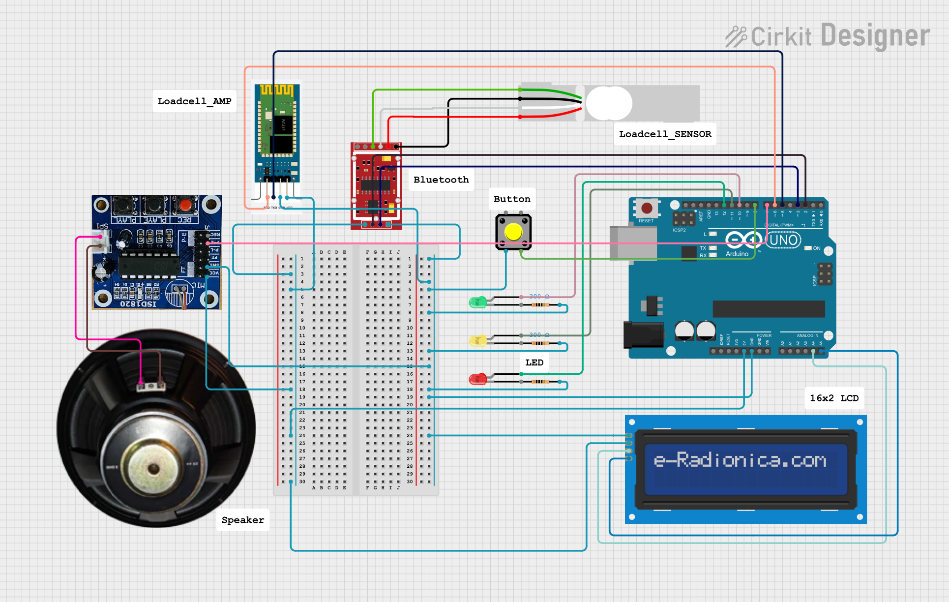
This circuit involves an Arduino UNO microcontroller interfacing with various components including an HX711 weighing sensor module, a load cell, an HC-06 Bluetooth module, an LCD screen, multiple LEDs, a pushbutton, a speaker controller, and a speaker. The circuit is designed to measure weight, display information on an LCD, and provide feedback through LEDs and a speaker. Additionally, it includes Bluetooth communication capabilities.
Component List
Arduino UNO
- Description: A microcontroller board based on the ATmega328P.
- Pins: UNUSED, IOREF, Reset, 3.3V, 5V, GND, Vin, A0, A1, A2, A3, A4, A5, SCL, SDA, AREF, D13, D12, D11, D10, D9, D8, D7, D6, D5, D4, D3, D2, D1, D0
HX711 Weighing Sensor Module
- Description: A precision 24-bit analog-to-digital converter (ADC) designed for weigh scales and industrial control applications.
- Pins: B-, B+, A-, A+, E-, E+, VCC, CK/TX, DO/RX, GND
Load Cell - Red/white/black/green
- Description: A sensor that measures force or weight.
- Pins: E+, A-, E-, A+
HC-06
- Description: A Bluetooth module for wireless communication.
- Pins: RXD, TXD, GND, VCC
LCD screen 16x2 I2C
- Description: A 16x2 character LCD display with I2C interface.
- Pins: SCL, SDA, VCC, GND
LED: Two Pin (red)
- Description: A red LED with two pins.
- Pins: cathode, anode
LED: Two Pin (yellow)
- Description: A yellow LED with two pins.
- Pins: cathode, anode
LED: Two Pin (green)
- Description: A green LED with two pins.
- Pins: cathode, anode
Resistor (300 Ohms)
- Description: A resistor with a resistance of 300 Ohms.
- Pins: pin1, pin2
Pushbutton
- Description: A simple pushbutton switch.
- Pins: Pin 2, Pin 1, Pin 3, Pin 4
Speaker Controller
- Description: A controller for driving a speaker.
- Pins: VCC, GND, P-E, REC, SP1 +, SP1 -, MIC +, MIC -
Speaker
- Description: A speaker for audio output.
- Pins: +, -
Wiring Details
Arduino UNO
5V connected to:
- HX711 Weighing Sensor Module (VCC)
- HC-06 (VCC)
- Speaker Controller (VCC)
- LCD screen 16x2 I2C (VCC)
GND connected to:
- HX711 Weighing Sensor Module (GND)
- HC-06 (GND)
- Pushbutton (Pin 2)
- Resistor (pin2)
- Resistor (pin2)
- Speaker Controller (GND)
- Resistor (pin2)
- LCD screen 16x2 I2C (GND)
A4 connected to:
- LCD screen 16x2 I2C (SDA)
A5 connected to:
- LCD screen 16x2 I2C (SCL)
D12 connected to:
- LED: Two Pin (red) (anode)
D11 connected to:
- LED: Two Pin (yellow) (anode)
D10 connected to:
- LED: Two Pin (green) (anode)
D8 connected to:
- Pushbutton (Pin 3)
D7 connected to:
- Speaker Controller (P-E)
D6 connected to:
- HC-06 (RXD)
D5 connected to:
- HC-06 (TXD)
D3 connected to:
- HX711 Weighing Sensor Module (DO/RX)
D2 connected to:
- HX711 Weighing Sensor Module (CK/TX)
HX711 Weighing Sensor Module
VCC connected to:
- Arduino UNO (5V)
GND connected to:
- Arduino UNO (GND)
DO/RX connected to:
- Arduino UNO (D3)
CK/TX connected to:
- Arduino UNO (D2)
A- connected to:
- Load Cell (A+)
A+ connected to:
- Load Cell (A-)
E- connected to:
- Load Cell (E+)
E+ connected to:
- Load Cell (E-)
Load Cell
A+ connected to:
- HX711 Weighing Sensor Module (A-)
A- connected to:
- HX711 Weighing Sensor Module (A+)
E+ connected to:
- HX711 Weighing Sensor Module (E-)
E- connected to:
- HX711 Weighing Sensor Module (E+)
HC-06
VCC connected to:
- Arduino UNO (5V)
GND connected to:
- Arduino UNO (GND)
RXD connected to:
- Arduino UNO (D6)
TXD connected to:
- Arduino UNO (D5)
LCD screen 16x2 I2C
VCC connected to:
- Arduino UNO (5V)
GND connected to:
- Arduino UNO (GND)
SDA connected to:
- Arduino UNO (A4)
SCL connected to:
- Arduino UNO (A5)
LED: Two Pin (red)
- anode connected to:
- Arduino UNO (D12)
LED: Two Pin (yellow)
- anode connected to:
- Arduino UNO (D11)
LED: Two Pin (green)
- anode connected to:
- Arduino UNO (D10)
Pushbutton
Pin 2 connected to:
- Arduino UNO (GND)
Pin 3 connected to:
- Arduino UNO (D8)
Speaker Controller
VCC connected to:
- Arduino UNO (5V)
GND connected to:
- Arduino UNO (GND)
P-E connected to:
- Arduino UNO (D7)
SP1 + connected to:
- Speaker (+)
SP1 - connected to:
- Speaker (-)
Speaker
+ connected to:
- Speaker Controller (SP1 +)
- connected to:
- Speaker Controller (SP1 -)
Documented Code
Arduino UNO Code (sketch.ino)
void setup() {
  // put your setup code here, to run once:

}

void loop() {
  // put your main code here, to run repeatedly:

}
Additional Documentation (documentation.txt)
This documentation provides a comprehensive overview of the circuit, including a detailed list of components, their connections, and the code used in the microcontroller.