
Circuit Documentation
Summary
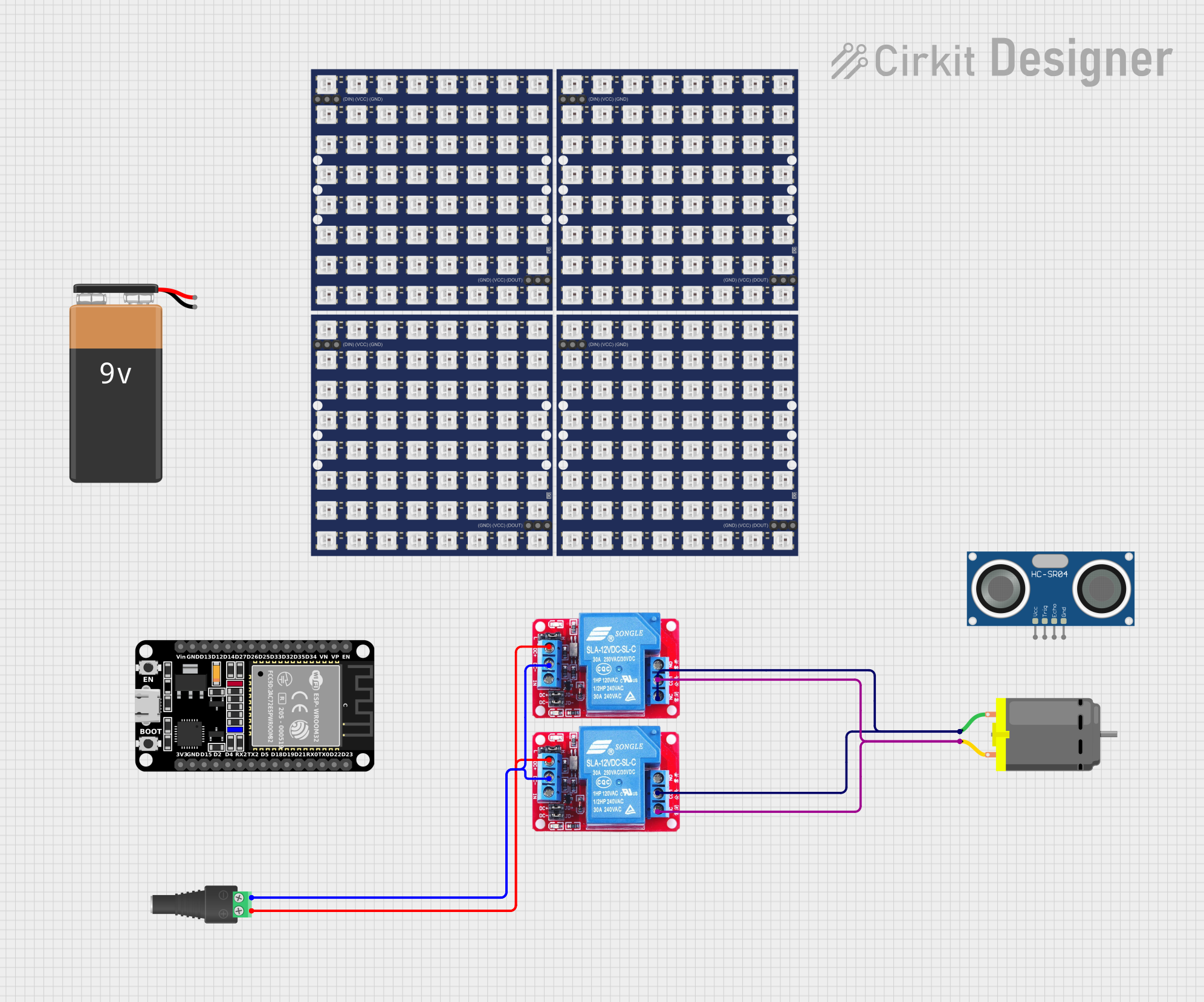
This circuit involves the use of two 12V relays, a DC motor, a 2.1mm barrel jack with a terminal block, and various other components. The relays control the DC motor, and the power is supplied through the barrel jack. The circuit is designed to manage the operation of the DC motor using the relays.
Component List
12V Relay
- Pins: NO, COM, NC, DC+, DC-, IN
- Description: A relay that operates at 12V to control high-power devices.
DC Motor
- Pins: pin 1, pin 2
- Description: A motor that runs on direct current.
WS2812 RGB LED Matrix 8x8
- Pins: DIN, VCC, GND, DOUT
- Description: An 8x8 matrix of WS2812 RGB LEDs.
ESP32 (30 pin)
- Pins: EN, VP, VN, D34, D35, D32, D33, D25, D26, D27, D14, D12, D13, GND, Vin, D23, D22, TX0, RX0, D21, D19, D18, D5, TX2, RX2, D4, D2, D15, 3V3
- Description: A microcontroller with Wi-Fi and Bluetooth capabilities.
2.1mm Barrel Jack with Terminal Block
- Pins: POS, NEG
- Description: A barrel jack for power input with a terminal block for easy connections.
HC-SR04 Ultrasonic Sensor
- Pins: VCC, TRIG, ECHO, GND
- Description: An ultrasonic sensor for distance measurement.
9V Battery
- Pins: -, +
- Description: A 9V battery for power supply.
Wiring Details
12V Relay 1
- NC: Connected to COM of 12V Relay 2 and pin 2 of DC Motor.
- COM: Connected to NC of 12V Relay 2 and pin 1 of DC Motor.
- DC+: Connected to DC+ of 12V Relay 2 and POS of 2.1mm Barrel Jack with Terminal Block.
- DC-: Connected to DC- of 12V Relay 2 and NEG of 2.1mm Barrel Jack with Terminal Block.
12V Relay 2
- NC: Connected to COM of 12V Relay 1 and pin 1 of DC Motor.
- COM: Connected to NC of 12V Relay 1 and pin 2 of DC Motor.
- DC+: Connected to DC+ of 12V Relay 1 and POS of 2.1mm Barrel Jack with Terminal Block.
- DC-: Connected to DC- of 12V Relay 1 and NEG of 2.1mm Barrel Jack with Terminal Block.
DC Motor
- pin 1: Connected to COM of 12V Relay 2 and NC of 12V Relay 1.
- pin 2: Connected to COM of 12V Relay 1 and NC of 12V Relay 2.
WS2812 RGB LED Matrix 8x8
- DIN: Not connected in the provided net list.
- VCC: Not connected in the provided net list.
- GND: Not connected in the provided net list.
- DOUT: Not connected in the provided net list.
ESP32 (30 pin)
- EN: Not connected in the provided net list.
- VP: Not connected in the provided net list.
- VN: Not connected in the provided net list.
- D34: Not connected in the provided net list.
- D35: Not connected in the provided net list.
- D32: Not connected in the provided net list.
- D33: Not connected in the provided net list.
- D25: Not connected in the provided net list.
- D26: Not connected in the provided net list.
- D27: Not connected in the provided net list.
- D14: Not connected in the provided net list.
- D12: Not connected in the provided net list.
- D13: Not connected in the provided net list.
- GND: Not connected in the provided net list.
- Vin: Not connected in the provided net list.
- D23: Not connected in the provided net list.
- D22: Not connected in the provided net list.
- TX0: Not connected in the provided net list.
- RX0: Not connected in the provided net list.
- D21: Not connected in the provided net list.
- D19: Not connected in the provided net list.
- D18: Not connected in the provided net list.
- D5: Not connected in the provided net list.
- TX2: Not connected in the provided net list.
- RX2: Not connected in the provided net list.
- D4: Not connected in the provided net list.
- D2: Not connected in the provided net list.
- D15: Not connected in the provided net list.
- 3V3: Not connected in the provided net list.
2.1mm Barrel Jack with Terminal Block
- POS: Connected to DC+ of 12V Relay 1 and DC+ of 12V Relay 2.
- NEG: Connected to DC- of 12V Relay 1 and DC- of 12V Relay 2.
HC-SR04 Ultrasonic Sensor
- VCC: Not connected in the provided net list.
- TRIG: Not connected in the provided net list.
- ECHO: Not connected in the provided net list.
- GND: Not connected in the provided net list.
9V Battery
- -: Not connected in the provided net list.
- +: Not connected in the provided net list.
Code
No code is provided for this circuit.