
Circuit Documentation
Summary of the Circuit
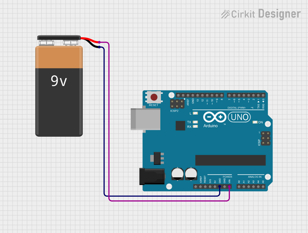
This circuit consists of a 9V battery connected to an Arduino UNO microcontroller. The battery provides power to the Arduino, which can be programmed to perform various tasks. The circuit is simple and serves as a foundational setup for powering the Arduino with a 9V battery.
Component List
9V Battery
- Description: A standard 9V battery used as a power source.
- Pins: Negative (-) and Positive (+)
Arduino UNO
- Description: A microcontroller board based on the ATmega328P. It has digital input/output pins, analog inputs, a USB connection for programming the board, a power jack, an ICSP header, and a reset button.
- Pins: UNUSED, IOREF, Reset, 3.3V, 5V, GND, Vin, A0-A5, SCL, SDA, AREF, D0-D13
Wiring Details
9V Battery
- Negative (-) Pin: Connected to the GND pin of the Arduino UNO.
- Positive (+) Pin: Connected to the Vin pin of the Arduino UNO.
Arduino UNO
- GND Pin: Connected to the negative (-) pin of the 9V Battery.
- Vin Pin: Connected to the positive (+) pin of the 9V Battery.
Documented Code
Arduino UNO Code (sketch.ino)
void setup() {
  // put your setup code here, to run once:

}

void loop() {
  // put your main code here, to run repeatedly:

}
Additional Notes
- The provided code is a template with empty
setup()andloop()functions. Thesetup()function is intended to contain initialization code that runs once when the Arduino is powered on or reset. Theloop()function is meant for code that runs continuously as long as the Arduino is powered. - The code file is named
sketch.ino, which is the default naming convention for Arduino sketches. - There is an additional text file (
documentation.txt) mentioned, but it appears to be empty and thus is not included in this documentation.
This concludes the documentation for the provided circuit design. The circuit is currently set up for basic power delivery to the Arduino UNO, and the microcontroller is ready to be programmed for specific applications.