
Circuit Documentation
Summary of the Circuit
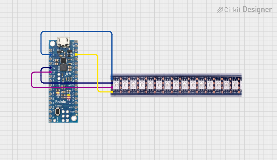
This circuit consists of an A-Star 32U4 Mini microcontroller board that controls an LED Strip. The A-Star 32U4 Mini is responsible for providing power to the LED Strip and for controlling its color and brightness via digital signals. The LED Strip receives its power from the 5V output of the microcontroller and shares a common ground. The control signals for the LED Strip are connected to specific GPIO pins on the A-Star 32U4 Mini.
Component List
A-Star 32U4 Mini
- Description: A compact microcontroller board based on the ATmega32U4.
- Pins: GND, 5V, 3V3, 13, 12, 11, 10, 9, 8, 7, 6, 5, 4, 3, 2, 1, 0, + BAT, - BAT, VIN, A0, A1, A2, A3, A4, A5, AREF, TXL, RXL, SCK, MOSI, MISO, RST.
- Purpose: Acts as the central controller for the circuit, providing power and signal control to the LED Strip.
LED Strip
- Description: A strip of LEDs that can be controlled to display various colors and patterns.
- Pins: VCC, CI, DI, GND.
- Purpose: Displays lighting effects as commanded by the A-Star 32U4 Mini.
Wiring Details
A-Star 32U4 Mini
- 5V connected to LED Strip VCC.
- GND connected to LED Strip GND.
- Pin 12 connected to LED Strip CI (Clock Input).
- Pin 11 connected to LED Strip DI (Data Input).
LED Strip
- VCC connected to A-Star 32U4 Mini 5V.
- GND connected to A-Star 32U4 Mini GND.
- CI connected to A-Star 32U4 Mini Pin 12.
- DI connected to A-Star 32U4 Mini Pin 11.
Documented Code
There is no code provided for the microcontroller. To control the LED Strip, code must be written and uploaded to the A-Star 32U4 Mini. The code should initialize the appropriate pins as outputs and use a suitable protocol (such as SPI or a custom bit-banging method) to send color and brightness data to the LED Strip.