
Circuit Documentation
Summary
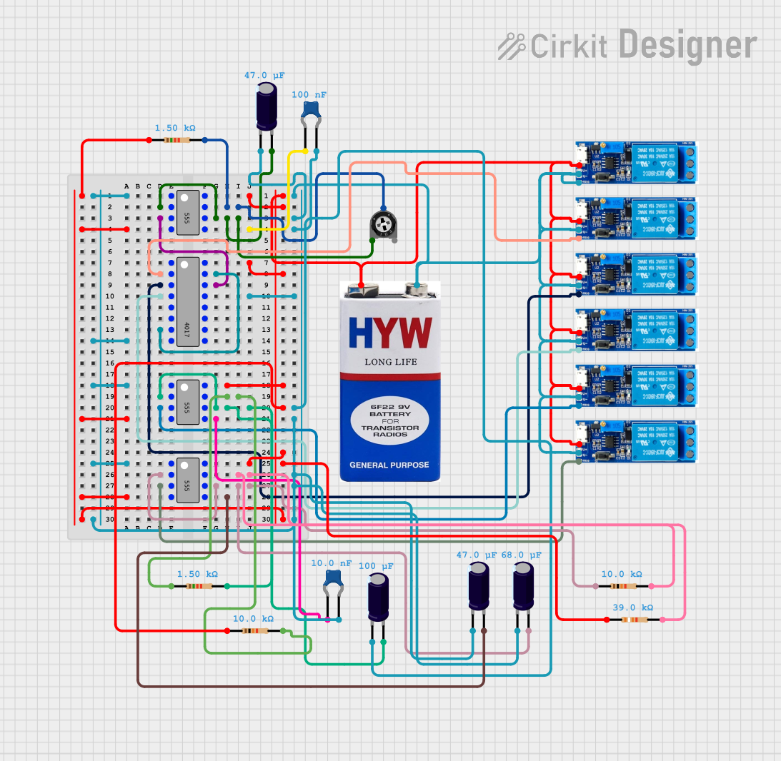
This circuit appears to be a sequential relay controller utilizing multiple 555 timers in conjunction with a 4017 decade counter to drive a series of relay modules. The 555 timers are likely configured in astable or monostable modes to generate timing signals or pulses. The 4017 counter advances its output with each pulse from the 555 timer, activating the relay modules in sequence. The circuit is powered by a 9V battery and includes various resistors and capacitors for timing control and noise suppression.
Component List
Integrated Circuits
- 555 Timer ICs: Three instances of the 555 timer IC are used, which can be configured for generating precise time delays or oscillations.
- 4017 Decade Counter IC: A counter that advances the "on" output in a sequence from one pin to the next with each input pulse.
Power Supply
- 9V Battery: Provides the power source for the circuit.
Passive Components
- Ceramic Capacitors: Used for noise suppression and timing control in conjunction with the 555 timers.
- Electrolytic Capacitors: Used for timing control with the 555 timers and potentially for power supply smoothing.
- Resistors: Various resistors are used for setting the timing characteristics of the 555 timers and for pull-up/pull-down configurations.
- Trimmer Potentiometer: An adjustable resistor that allows for fine-tuning the timing characteristics of the 555 timer circuit.
Electromechanical Components
- Relay Modules (5v-30v): Used to control higher power loads sequentially, driven by the outputs of the 4017 counter.
Wiring Details
555 Timer ICs
- Ground (GND): Connected to the negative terminal of the 9V battery and common ground.
- Trigger (TRIG) and Threshold (THR): Connected together and to a timing capacitor.
- Output (OUT): Drives the clock input of the 4017 counter or triggers a relay module.
- Reset (~RESET): Tied to VCC for normal operation.
- Control Voltage (CTRL): Connected to a capacitor for stability.
- Discharge (DIS): Connected to a timing resistor and the wiper of a potentiometer.
- Supply Voltage (VCC): Connected to the positive terminal of the 9V battery.
4017 Decade Counter IC
- Ground (GND): Connected to common ground.
- Supply Voltage (VCC): Connected to the positive terminal of the 9V battery.
- Clock (CLK): Driven by the output of a 555 timer.
- Reset (MR): Connected to an output to reset the counter at a specific count.
- Enable (~EN): Tied to ground to enable the counter.
- Outputs (Q0-Q9): Connected to relay modules to control sequential activation.
Relay Modules
- Trigger: Activated by the output of the 4017 counter or a 555 timer.
- Common Contact, Normally Open, Normally Closed: Used to switch connected loads.
- Supply Voltage (V+): Connected to the positive terminal of the 9V battery.
- Ground (V-): Connected to common ground.
Resistors and Capacitors
- Timing Resistors: Connected to the discharge pin of the 555 timers and used to set the timing interval.
- Timing Capacitors: Connected between the trigger/threshold pins of the 555 timers and ground, used to set the timing interval.
- Noise Suppression Capacitors: Connected to the control voltage pin of the 555 timers.
Trimmer Potentiometer
- Legs: Connected to the discharge pin of a 555 timer and a timing resistor.
- Wiper: Connected to the discharge pin of the 555 timer.
Documented Code
No code has been provided for any microcontrollers in this circuit. The circuit functions are likely controlled purely by the hardware configuration of the 555 timers and the 4017 counter without the need for software intervention.