Cirkit Designer
Your all-in-one circuit design IDE
Home /
Project Documentation
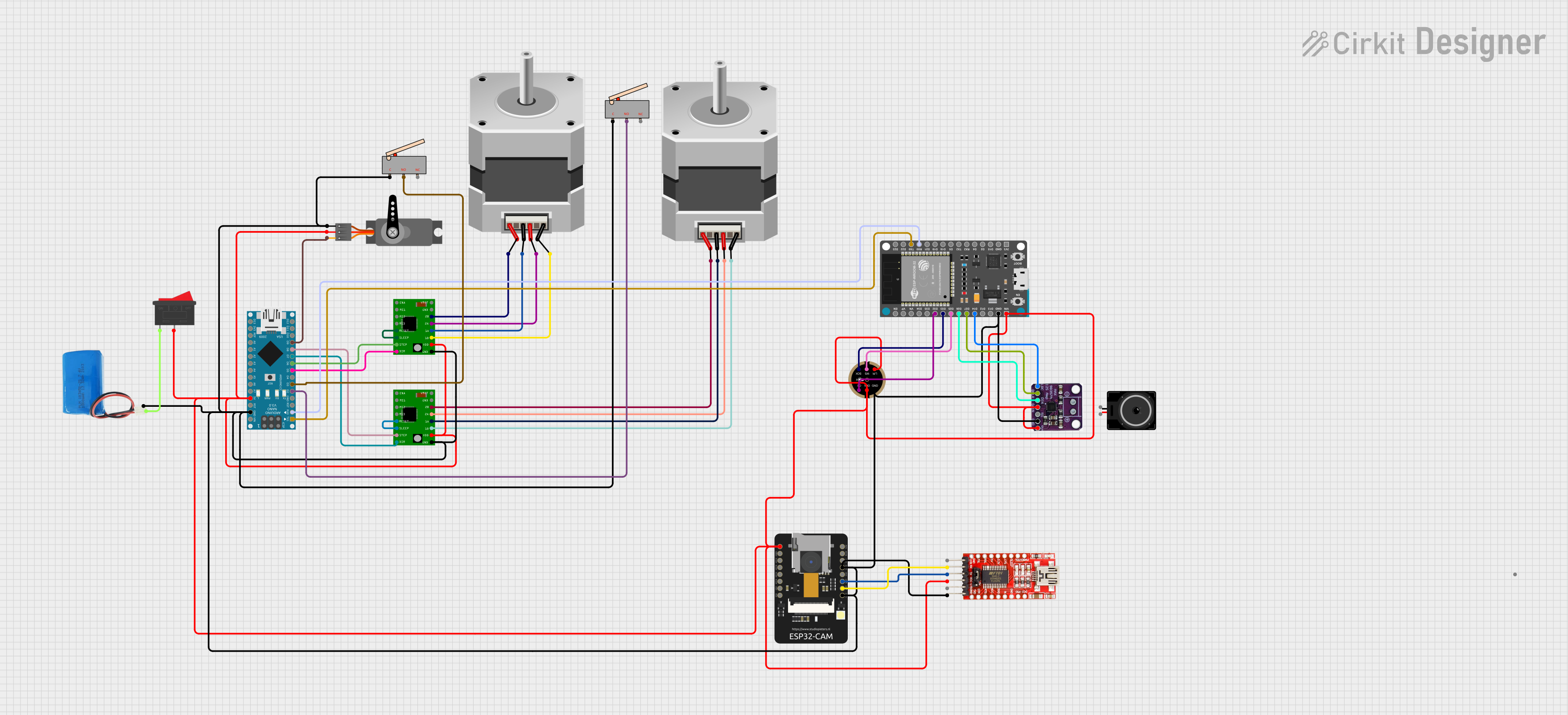
ESP32-CAM and Arduino Nano Controlled CNC Machine with Wi-Fi Capability
Circuit Documentation
Summary
This circuit is designed to control a CNC machine with stepper motors, a servo motor, and an ESP32-CAM module for capturing images. The Arduino Nano serves as the primary controller, interfacing with stepper motor drivers, limit switches, and a servo motor. The ESP32-CAM module is used for wireless communication and image capture. The circuit includes a microphone for audio input and a digital amplifier for audio output. Power management is handled by a 5V battery connected through a rocker switch.
Component List
A4988 Stepper Motor Driver Carrier
- Description: A compact driver for controlling stepper motors in microstepping mode.
- Pins: ENABLE, MS1, MS2, MS3, RESET, SLEEP, STEP, DIR, GND, VCC, 1B, 1A, 2A, 2B, VMOT
Stepper Motor (Bipolar)
- Description: A bipolar stepper motor for precise motion control.
- Pins: D, B, C, A
ESP32 - CAM
- Description: A small-sized ESP32-based board with camera and Wi-Fi capabilities.
- Pins: 5V, GND, IO12, IO13, IO15, IO14, IO2, IO4, VOT, VOR, VCC, IO0, IO16, 3V3
INMP441 FRONT MIC
- Description: A digital I2S output microphone with high signal-to-noise ratio.
- Pins: L/R, WS, SCK, SD, VDD, GND
Loudspeaker
- Description: An audio output device for sound playback.
- Pins: pin1, pin2
5v Battery
- Description: A power source for the circuit.
- Pins: positive, negative
Rocker Switch
- Description: A switch to control the power supply to the circuit.
- Pins: 1, 2
MAX98375
- Description: A digital audio amplifier with I2S input.
- Pins: LRC, BLCK, DIN, GAIN, SD, GND, VIN
FTDI Programmer
- Description: A USB to serial converter for programming microcontrollers.
- Pins: DTR, RX, TX, VCC, CTS, GND
Limit Switch
- Description: A switch that is actuated by the motion of a machine part or presence of an object.
- Pins: C, NO, NC
Arduino Nano
- Description: A small, complete, and breadboard-friendly board based on the ATmega328.
- Pins: D1/TX, D0/RX, RESET, GND, D2, D3, D4, D5, D6, D7, D8, D9, D10, D11/MOSI, D12/MISO, VIN, 5V, A7, A6, A5, A4, A3, A2, A1, A0, AREF, 3V3, D13/SCK
ESP32 Devkit V1
- Description: A development board with an ESP32 chip for Wi-Fi and Bluetooth applications.
- Pins: 3V3, GND, D15, D2, D4, RX2, TX2, D5, D18, D19, D21, RX0, TX0, D22, D23, EN, VP, VN, D34, D35, D32, D33, D25, D26, D27, D14, D12, D13, VIN
Servo
- Description: A rotary actuator or linear actuator that allows for precise control of angular or linear position.
- Pins: GND, VCC, PWM
Wiring Details
A4988 Stepper Motor Driver Carrier
- ENABLE: Not connected
- MS1, MS2, MS3: Not connected (for microstepping configuration)
- RESET: Connected to SLEEP
- SLEEP: Connected to RESET
- STEP: Controlled by Arduino Nano (D6 or D8)
- DIR: Controlled by Arduino Nano (D5 or D7)
- GND: Common ground
- VCC: Connected to 5V supply
- 1B, 1A, 2A, 2B: Connected to corresponding stepper motor pins
- VMOT: Not specified (usually connected to motor power supply)
Stepper Motor (Bipolar)
- D, B, C, A: Connected to corresponding A4988 driver pins 1B, 1A, 2A, 2B
ESP32 - CAM
- 5V: Connected to 5V supply
- GND: Common ground
- IO12, IO13, IO15, IO14, IO2, IO4: Not specified
- VOT: Connected to FTDI Programmer RX
- VOR: Connected to FTDI Programmer TX
- VCC: Connected to 5V supply
- IO0, IO16: Not specified
- 3V3: Not specified
INMP441 FRONT MIC
- L/R: Connected to 5V supply
- WS: Connected to ESP32 Devkit V1 D25
- SCK: Connected to ESP32 Devkit V1 D33
- SD: Connected to ESP32 Devkit V1 D32
- VDD: Connected to 5V supply
- GND: Common ground
Loudspeaker
- pin1, pin2: Not specified (usually connected to an audio amplifier output)
5v Battery
- positive: Connected to the rocker switch
- negative: Common ground
Rocker Switch
- 1: Connected to 5V battery positive
- 2: Connected to circuit power input
MAX98375
- LRC: Connected to ESP32 Devkit V1 D14
- BLCK: Connected to ESP32 Devkit V1 D27
- DIN: Connected to ESP32 Devkit V1 D26
- GAIN: Connected to 5V supply
- SD: Not specified
- GND: Common ground
- VIN: Connected to 5V supply
FTDI Programmer
- DTR: Not specified
- RX: Connected to ESP32 - CAM VOT
- TX: Connected to ESP32 - CAM VOR
- VCC: Connected to 5V supply
- CTS: Not specified
- GND: Common ground
Limit Switch
- C: Common ground
- NO: Connected to Arduino Nano D2 or D3
- NC: Not connected
Arduino Nano
- D1/TX: Connected to ESP32 Devkit V1 TX0
- D0/RX: Connected to ESP32 Devkit V1 RX0
- RESET, AREF, 3V3: Not specified
- GND: Common ground
- D2, D3: Connected to limit switches NO
- D5, D6, D7, D8: Control A4988 drivers DIR and STEP
- D9: Connected to Servo PWM
- D10, D11/MOSI, D12/MISO, D13/SCK: Not specified
- VIN, 5V: Connected to 5V supply
- A0-A7: Not specified
ESP32 Devkit V1
- 3V3, EN, VP, VN, D34, D35, D15, D2, D4, RX2, TX2, D5, D18, D19, D21, D22, D23: Not specified
- GND: Common ground
- RX0: Connected to Arduino Nano D0/RX
- TX0: Connected to Arduino Nano D1/TX
- D25, D26, D27, D14, D32, D33: Connected to INMP441 FRONT MIC and MAX98375
- D12, D13: Not specified
- VIN: Connected to 5V supply
Servo
- GND: Common ground
- VCC: Connected to 5V supply
- PWM: Controlled by Arduino Nano D9
Documented Code
ESP32 - CAM Code (sketch.ino)
#include <WebServer.h>
#include <WiFi.h>
#include <esp32cam.h>

const char* WIFI_SSID = "Your SSID";
const char* WIFI_PASS = "Your Password";

WebServer server(80);

static auto loRes = esp32cam::Resolution::find(320, 240);
static auto midRes = esp32cam::Resolution::find(350, 530);
static auto hiRes = esp32cam::Resolution::find(800, 600);

void serveJpg()
{
  auto frame = esp32cam::capture();
  if (frame == nullptr) {
    Serial.println("CAPTURE FAIL");
    server.send(503, "", "");
    return;
  }
  Serial.printf("CAPTURE OK %dx%d %db", frame->getWidth(), frame->getHeight(),
                static_cast<int>(frame->size()));

  server.setContentLength(frame->size());
  server.send(200, "image/jpeg");
  WiFiClient client = server.client();
  frame->writeTo(client);
}

void handleJpgLo()
{