
Arduino Mega 2560 Controlled RFID and IR Sensor Array with Servo and Dual I2C LCD Displays
View and Edit Project In Cirkit Designer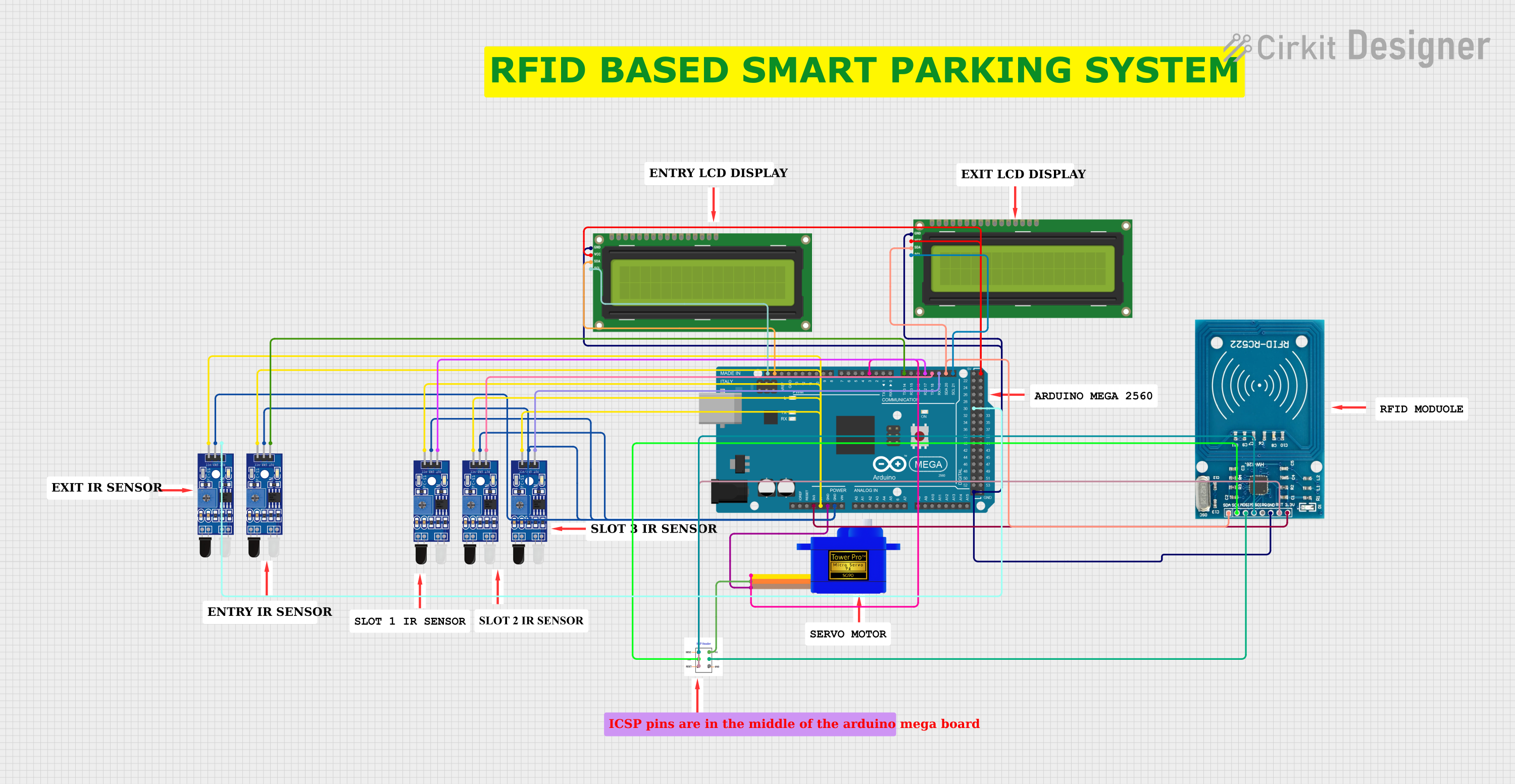
Circuit Documentation
Summary
This document provides a detailed overview of a circuit that includes an Arduino Mega 2560 microcontroller, multiple IR sensors (Sensor FC-51 IR), an RFID module (RFID-RC522), a servomotor (Servomotor SG90), and two I2C LCD 16x2 screens. The circuit is designed to interface with various sensors and modules to perform tasks that may include detection, identification, and display of information. The Arduino Mega 2560 serves as the central processing unit, controlling the sensors, the RFID reader, and the servomotor, as well as communicating with the LCD screens via the I2C protocol.
Component List
- Arduino Mega 2560: A microcontroller board based on the ATmega2560, with numerous digital and analog I/O pins.
- Sensor FC-51 IR: An infrared sensor module used for object detection.
- RFID-RC522: An RFID reader module for reading RFID tags.
- Servomotor SG90: A small and lightweight servomotor for precise angular movement.
- I2C LCD 16x2 Screen: A 16x2 character LCD display that uses the I2C communication protocol.
Wiring Details
Arduino Mega 2560
- 3V3: Powers the RFID-RC522 module.
- 5V: Powers the IR sensors and the I2C LCD screens.
- GND: Common ground for the servomotor, IR sensors, RFID-RC522, and I2C LCD screens.
- D21/SCL: I2C clock line connected to the SCL pin of the I2C LCD screen.
- D20/SDA: I2C data line connected to the SDA pin of the I2C LCD screen and the SDA pin of the RFID-RC522.
- D19/RX1: Receives data from one of the IR sensors.
- D18/TX1: Transmits data to one of the IR sensors.
- D17 PWM/RX2: Receives data from one of the IR sensors.
- D14/TX3: Transmits data to one of the IR sensors.
- D3 PWM: PWM output to control the servomotor.
- D30: Digital input from one of the IR sensors.
Sensor FC-51 IR
- VCC: Powered by the 5V output from the Arduino Mega 2560.
- GND: Connected to the common ground.
- OUT: Outputs the sensor signal to various digital pins on the Arduino Mega 2560 (D19/RX1, D18/TX1, D17 PWM/RX2, D14/TX3, D30).
RFID-RC522
- VCC (3.3V): Powered by the 3V3 output from the Arduino Mega 2560.
- RST: Reset pin connected to the ICSP RST pin.
- GND: Connected to the common ground.
- IRQ: Not connected in this circuit.
- MISO: SPI MISO line connected to the ICSP MISO pin.
- MOSI: SPI MOSI line connected to the ICSP MOSI pin.
- SCK: SPI clock line connected to the ICSP SCK pin.
- SDA: I2C data line connected to the D20/SDA pin on the Arduino Mega 2560.
Servomotor SG90
- SIG: Signal pin connected to the D3 PWM pin on the Arduino Mega 2560.
- VCC: Powered by the ICSP VCC pin.
- GND: Connected to the common ground.
I2C LCD 16x2 Screen
- SCL: I2C clock line connected to the D21/SCL pin on the Arduino Mega 2560.
- SDA: I2C data line connected to the D20/SDA pin on the Arduino Mega 2560.
- VCC (5V): Powered by the 5V output from the Arduino Mega 2560.
- GND: Connected to the common ground.
Documented Code
Arduino Mega 2560
sketch.ino
void setup() {
  // put your setup code here, to run once:

}

void loop() {
  // put your main code here, to run repeatedly:

}
documentation.txt
No additional code documentation provided.
(Note: The actual functionality of the code is not provided in the input, so the code section only includes the template for an Arduino sketch. Additional code would be necessary to control the components as described in the wiring details.)