SparkFun Pro Micro Based Motion Tracking System with BMI160 and EEPROM Data Logging
Circuit Documentation
Summary
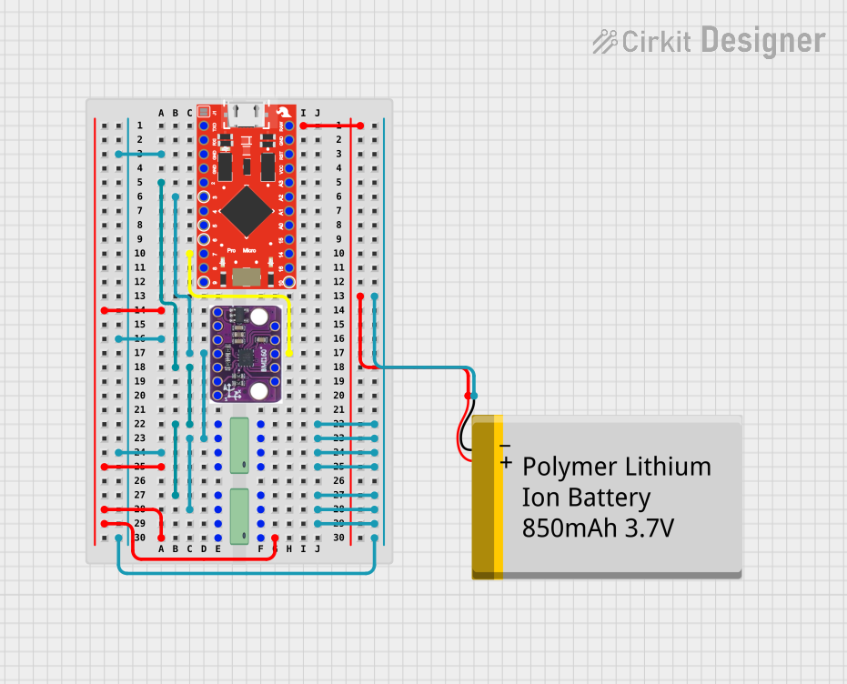
The circuit in question is designed to interface a SparkFun Pro Micro microcontroller with a BMI160 6DOF sensor and two 24LC512 EEPROM chips. It is powered by a Polymer Lithium Ion Battery with a capacity of 850mAh. The Pro Micro is responsible for processing data from the BMI160 sensor and communicating with the EEPROM chips via I2C protocol. The battery provides the necessary power to the microcontroller and other components. The circuit is likely intended for applications requiring motion tracking and data storage capabilities.
Component List
SparkFun Pro Micro
- Microcontroller board based on the ATmega32U4
- Operates at 5V/16MHz
- Equipped with 18 digital I/O pins and 12 analog inputs
24LC512 EEPROM (x2)
- 512Kbit Electrically Erasable PROM
- I2C interface
- 64-byte page write buffer
BMI160 Accelerometer Gyro - 6DOF sensor
- Inertial Measurement Unit (IMU) with a 3-axis accelerometer and a 3-axis gyroscope
- I2C/SPI interface
- Interrupt pins for motion detection
Polymer Lithium Ion Battery - 850mAh
- Rechargeable battery
- Provides power to the circuit
Wiring Details
SparkFun Pro Micro
RAWconnected to the positive terminal of the Polymer Lithium Ion BatteryGNDconnected to the ground plane of the circuitD2(SDA) andD3(SCL) connected to the I2C bus for communication with EEPROMs and BMI160 sensorD7connected to theINT1pin of the BMI160 sensor for interrupt-driven events
24LC512 EEPROM
A0,A1,A2connected to the ground plane for address selection (assuming address grounding)Vssconnected to the ground planeVccconnected to the positive voltage railWPconnected to the ground plane (write protection disabled)SCLandSDAconnected to the I2C bus
BMI160 Accelerometer Gyro - 6DOF sensor
GNDconnected to the ground planeVINconnected to the positive voltage railSDAandSCLconnected to the I2C busINT1connected toD7on the SparkFun Pro Micro for interrupts
Polymer Lithium Ion Battery - 850mAh
VCCconnected to theRAWpin of the SparkFun Pro MicroGNDconnected to the ground plane of the circuit
Documented Code
#include <BMI160Gen.h>
// Requires https://github.com/hanyazou/BMI160-Arduino

const int bmi160_i2c_addr = 0x69;
const int bmi160_interrupt_pin = 7;
bool running = false;
int RXLED = 17;

unsigned long miPoll, miPrint = 1000;

int16_t absx, absy, absz;
int ax, ay, az;
//int gx, gy, gz;

#define runEvery(t) for (static typeof(t) _lasttime; \
                         (typeof(t))((typeof(t))millis() - _lasttime) > (t); \
                         _lasttime += (t))

void bmi160_intr(void)
{
  running = !running;
  if(running) {
    digitalWrite(RXLED, LOW); // RX LED on!
    TXLED1; //TX LED ON Macro
  } else {
    digitalWrite(RXLED, HIGH); // RX LED on!
    TXLED0;
  }
}

void setup() {

  Serial.begin(9600);
  while (!Serial);

  // initialize device
  BMI160.begin(BMI160GenClass::I2C_MODE, bmi160_i2c_addr, bmi160_interrupt_pin);
  BMI160.attachInterrupt(bmi160_intr);
  BMI160.setIntDoubleTapEnabled(true);

  BMI160.autoCalibrateGyroOffset();
  BMI160.autoCalibrateXAccelOffset(0);
  BMI160.autoCalibrateYAccelOffset(0);
  BMI160.autoCalibrateZAccelOffset(1);
  BMI160.setGyroOffsetEnabled(true);
  BMI160.setAccelOffsetEnabled(true);

  miPoll = 1000/BMI160.getAccelerometerRate();

  digitalWrite(RXLED, HIGH);
  TXLED0;
}

void loop() {
  if (running) {
    runEvery(miPoll) {
      BMI160.readGyro(ax, ay, az);
      absx = absx + ax;
      absy = absy + ay;
      absz = absz + az;
    }
    runEvery(miPrint) {
      Serial.print(absx); Serial.print("\t");
      Serial.print(absy); Serial.print("\t");
      Serial.println(absz);
    }
  }
}
This code is designed to run on the SparkFun Pro Micro microcontroller. It initializes the BMI160 sensor, sets up interrupt handling for motion detection, and periodically reads gyroscopic data, outputting the accumulated values over the serial connection. The LED indicators are used to signal the running state of the device.