Arduino Mega 2560 Controlled Robotic Arm with ESP8266 Wi-Fi Connectivity and Audio Feedback
Circuit Documentation
Summary
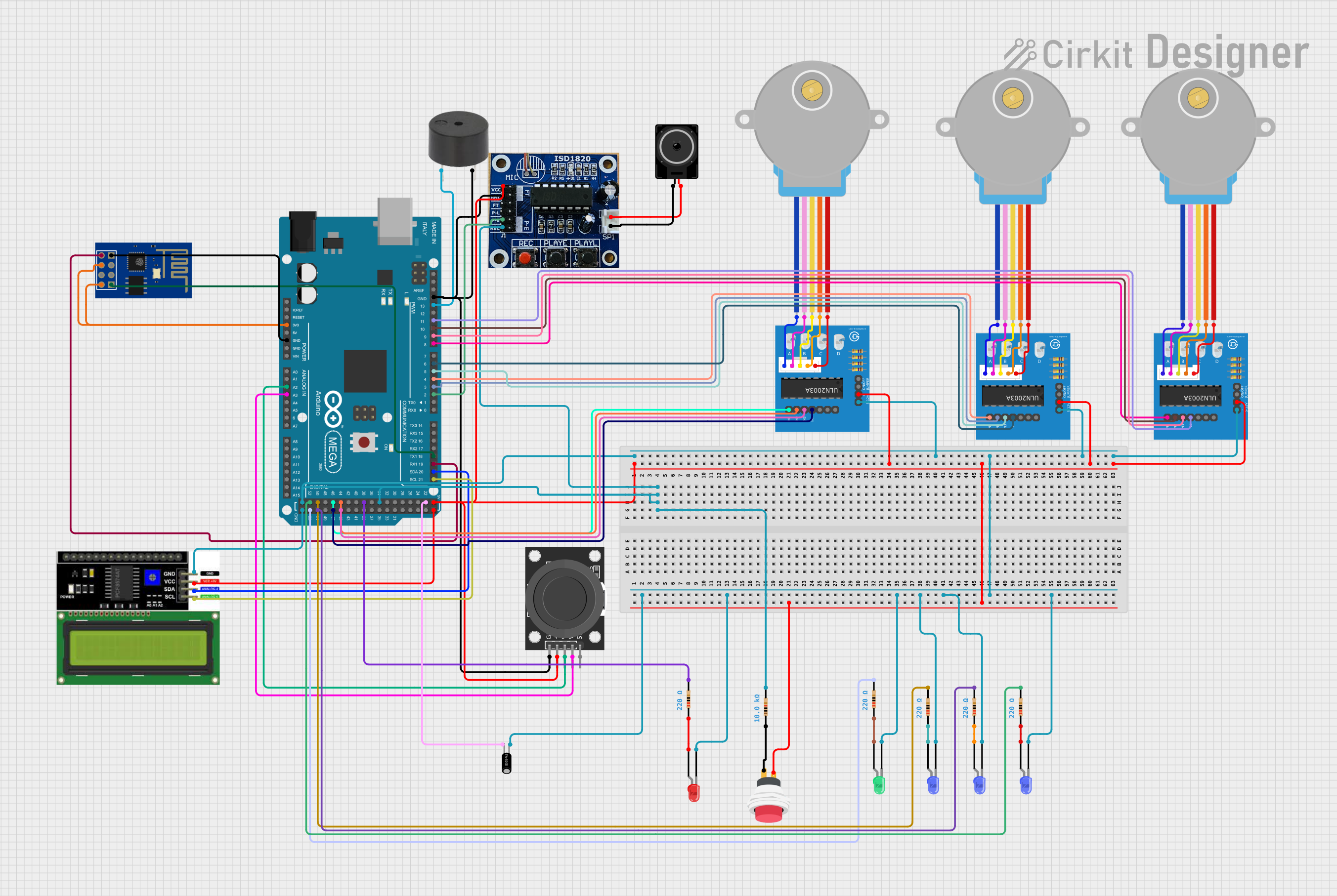
This circuit integrates various components including microcontrollers, sensors, actuators, and interface modules to create a multifunctional system. The core of the circuit is an Arduino Mega 2560, which interfaces with an ESP8266 ESP-01 WiFi module for wireless connectivity, a speaker system for audio output, a dual-axis joystick for input, an LCD display for visual feedback, and several LEDs and motors for additional interaction. The circuit is designed to be versatile, with the potential for applications ranging from automation to interactive projects.
Component List
Microcontrollers
- Arduino Mega 2560: A microcontroller board based on the ATmega2560 with numerous digital and analog I/O pins.
Communication Modules
- ESP8266 ESP-01 WiFi Module: A self-contained Wi-Fi networking solution offering a wide range of connectivity options.
Actuators
- Loudspeaker: An electroacoustic transducer used to produce sound.
- 28BYJ-48 Stepper Motors: Small, affordable stepper motors suitable for a wide range of motion control applications.
Interface Modules
- ULN2003A Breakout Boards: Boards designed to drive stepper motors, featuring a ULN2003A Darlington transistor array.
- Speaker Controller: A module for controlling a speaker, with inputs for recording and playback.
- LCD I2C Display: A liquid crystal display with an I2C interface for showing textual information.
- KY-023 Dual Axis Joystick Module: A module with a joystick providing two analog outputs corresponding to the X and Y axes and a digital output for the joystick switch.
Sensors
- Tilt Sensor: A sensor that detects orientation or inclination.
Passive Components
- Resistors: Components used to limit current or divide voltages in the circuit. Various resistances are used, including 220 Ohms and 10,000 Ohms.
- 2Pin Push Switch: A simple switch that connects or disconnects the circuit.
- LEDs: Light Emitting Diodes of different colors (red, green, blue) used as visual indicators.
Sound Devices
- Buzzer: An audio signaling device that can be used to create beeps or alerts.
Wiring Details
Arduino Mega 2560
- Connected to the ESP8266 ESP-01 WiFi Module for serial communication.
- Powers the Speaker Controller, KY-023 Joystick, ULN2003A Breakout Boards, and LCD I2C Display.
- Interfaces with the Speaker Controller for audio playback control.
- Receives analog input from the KY-023 Joystick.
- Communicates with the LCD I2C Display via I2C protocol.
- Drives the ULN2003A Breakout Boards to control the stepper motors.
- Controls the buzzer and tilt sensor.
- Connected to various LEDs through resistors.
ESP8266 ESP-01 WiFi Module
- Receives power from the Arduino Mega 2560.
- Communicates with the Arduino Mega 2560 via serial connection.
Loudspeaker
- Connected to the Speaker Controller for audio output.
ULN2003A Breakout Boards
- Receives signals from the Arduino Mega 2560 to drive the stepper motors.
- Connected to the stepper motors for controlling their movements.
Speaker Controller
- Receives power and control signals from the Arduino Mega 2560.
- Connected to the loudspeaker for audio output.
LCD I2C Display
- Powered by the Arduino Mega 2560.
- Uses I2C communication with the Arduino Mega 2560 for displaying information.
KY-023 Dual Axis Joystick Module
- Powered by the Arduino Mega 2560.
- Provides analog input to the Arduino Mega 2560.
Tilt Sensor
- Connected to the Arduino Mega 2560 for orientation detection.
Resistors
- Connected in series with LEDs to limit the current.
- One resistor is used for pull-up on a digital input.
LEDs
- Connected to the Arduino Mega 2560 through resistors.
Buzzer
- Controlled by the Arduino Mega 2560 for audio alerts.
Documented Code
void setup() {
  // put your setup code here, to run once:

}

void loop() {
  // put your main code here, to run repeatedly:

}
This code is a template for the Arduino Mega 2560 and does not contain any functional code. It provides the basic structure for an Arduino sketch with setup() and loop() functions, where initialization code is placed in setup() and the main code that runs repeatedly is placed in loop().