Cirkit Designer
Your all-in-one circuit design IDE
Home /
Project Documentation
Arduino Nano Controlled Dimmable LED Headlight with Dual LDR Sensors
Circuit Documentation
Summary
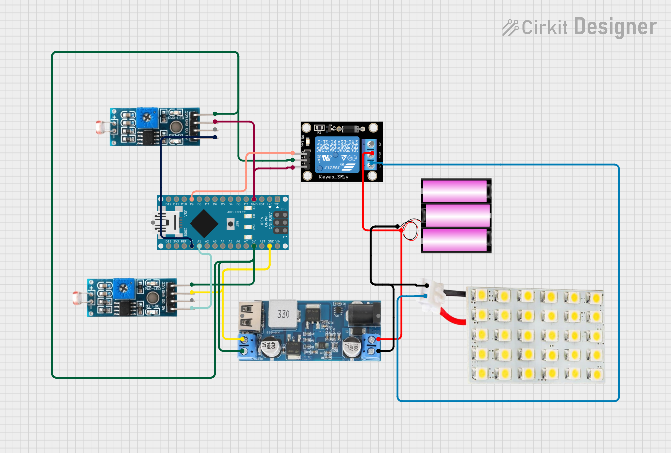
The circuit in question is designed to control an LED board based on the ambient light levels detected by two Light Dependent Resistors (LDRs). It utilizes an Arduino Nano as the central microcontroller to read the light levels from the LDRs and adjust the brightness of the LED accordingly. A relay module is used to switch the LED board on and off, and a 12V battery powers the system through a step-down power converter that provides the necessary 5V to the components.
Component List
Arduino Nano
- Microcontroller board based on the ATmega328P
- It has a variety of digital and analog I/O pins.
Module LDR (x2)
- Light Dependent Resistor module
- It has both analog and digital outputs.
Relay Module 1 Channel
- A single-channel relay module capable of controlling high power devices.
- It has a set of normally open (NO) and normally closed (NC) contacts.
Battery 12V
- A 12-volt battery providing the power source for the circuit.
LED Board
- A board with an LED that can be used as an indicator or a light source.
12V to 5V Step Down Power Converter
- A power converter that steps down the voltage from 12V to 5V.
Wiring Details
Arduino Nano
- GND connected to the common ground net.
- 5V connected to the 5V power net.
- D9 connected to the signal pin (S) of the Relay module.
- A0 connected to the analog output (AO) of the first Module LDR.
- A1 connected to the analog output (AO) of the second Module LDR.
Module LDR
- VCC connected to the 5V power net.
- GND connected to the common ground net.
- AO (of the first LDR) connected to A0 on the Arduino Nano.
- AO (of the second LDR) connected to A1 on the Arduino Nano.
Relay Module 1 Channel
- GND connected to the common ground net.
- S connected to D9 on the Arduino Nano.
- 5V connected to the 5V power net.
- COM connected to the positive terminal of the battery and VIN+ of the step-down converter.
- NO connected to the VCC of the LED Board.
Battery 12V
- + connected to the COM of the Relay module and VIN+ of the step-down converter.
- - connected to the common ground net.
LED Board
- VCC connected to the NO of the Relay module.
- GND connected to the common ground net.
12V to 5V Step Down Power Converter
- VIN 9v-36v / VIN+ connected to the positive terminal of the battery and COM of the Relay module.
- GND connected to the common ground net.
- 5v OUTPUT connected to the 5V power net.
Documented Code
int LDR1 = A0; // Pin connected to the first LDR
int LDR2 = A1; // Pin connected to the second LDR
int headlight = 9; // Pin connected to the headlight LED

void setup() {
 pinMode(headlight, OUTPUT);
 Serial.begin(9600);
}

void loop() {
 int lightLevel1 = analogRead(LDR1);
 int lightLevel2 = analogRead(LDR2);

 int threshold = 500; // Set this threshold according to your needs

 if (lightLevel1 > threshold || lightLevel2 > threshold) {
   analogWrite(headlight, 128); // Dim the headlights (50% brightness)
 } else {
   analogWrite(headlight, 255); // Full brightness
 }

 delay(100);
}
Code Explanation
- LDR1 and LDR2 are defined as analog input pins connected to the LDR modules.
- headlight is defined as the digital output pin connected to the relay module controlling the LED board.
- In
setup(), the headlight pin is set as an output and the serial communication is started. - In the
loop(), the light levels from both LDRs are read. - If either of the light levels is above the threshold, the LED brightness is set to 50%. Otherwise, it is set to full brightness.
- A delay of 100ms is added to the loop to stabilize readings.