Cirkit Designer
Your all-in-one circuit design IDE
Home /
Project Documentation
Arduino UNO-Based Battery-Powered Robotic Vehicle with Joystick Control
Circuit Documentation
Summary
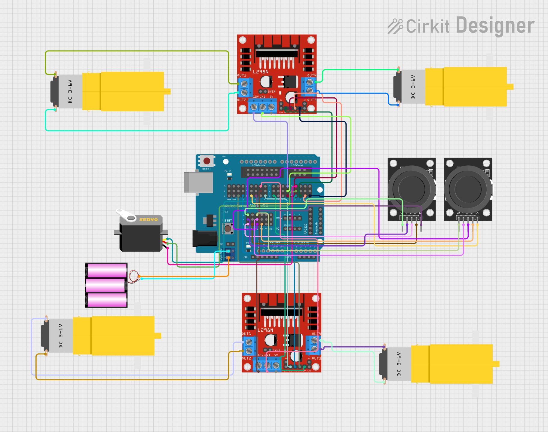
This document provides a detailed overview of a circuit that includes an Arduino UNO, an Arduino Sensor Shield v5.0, two L298N DC motor drivers, four hobby motors, a servo motor, a 12V battery, and two KY-023 Dual Axis Joystick Modules. The circuit is designed to control multiple motors and a servo using the Arduino platform, with input from joystick modules.
Component List
Arduino UNO
- Description: A microcontroller board based on the ATmega328P.
- Pins: UNUSED, IOREF, Reset, 3.3V, 5V, GND, Vin, A0, A1, A2, A3, A4, A5, SCL, SDA, AREF, D13, D12, D11, D10, D9, D8, D7, D6, D5, D4, D3, D2, D1, D0
Arduino Sensor Shield v5.0
- Description: A shield that provides easy connections for sensors and actuators.
- Pins: VCC, SD-VCC, SD-GND, SD-D11, SD-D10, SD-D13, SD-D12, URF01-VCC, URF01-A0, URF01-A1, URF01-GND, GND, SEL1, SEL2, A0-SIG, A0-VCC, A0-GND, A1-SIG, A1-VCC, A1-GND, A2-SIG, A2-VCC, A2-GND, A3-SIG, A3-VCC, A3-GND, A4-SIG, A4-VCC, A4-GND, A5-SIG, A5-VCC, A5-GND, IIC-SCL, IIC-SDA, IIC-GND, IIC-VCC, COM-TX, COM-RX, COM-GND, COM-VCC, APC220-, APC220-D0, APC220-D1, APC220-VCC, APC220-GND, BLUETOOTH-3V3, BLUETOOTH-GND, BLUETOOTH-D0, BLUETOOTH-D1, BLUETOOTH-VCC, AREF-S, AREF-V, AREF-G, GND-S, GND-V, GND-G, 13-S, 13-V, 13-G, 12-S, 12-V, 12-G, 11-S, 11-V, 11-G, 10-S, 10-V, 10-G, 9-S, 9-V, 9-G, 8-S, 8-V, 8-G, 7-S, 7-V, 7-G, 6-S, 6-V, 6-G, 5-S, 5-V, 5-G, 4-S, 4-V, 4-G, 3-S, 3-V, 3-G, 2-S, 2-V, 2-G, 1-S, 1-V, 1-G, 0-S, 0-V, 0-G, ParallelLCD-VCC, ParallelLCD-D13, ParallelLCD-GND, ParallelLCD-D12, ParallelLCD-D2, ParallelLCD-D11, ParallelLCD-D3, ParallelLCD-D10, ParallelLCD-D4, ParallelLCD-D9, ParallelLCD-D5, ParallelLCD-D8, ParallelLCD-D6, ParallelLCD-D7, SerialLCD-D4, SerialLCD-VCC, SerialLCD-D3, SerialLCD-, SerialLCD-D2, SerialLCD-GND
L298N DC Motor Driver
- Description: A dual H-bridge motor driver that allows control of two DC motors.
- Pins: OUT1, OUT2, 12V, GND, 5V, OUT3, OUT4, 5V-ENA-JMP-I, 5V-ENA-JMP-O, +5V-J1, +5V-J2, ENA, IN1, IN2, IN3, IN4, ENB
Motor amarillo motorreductor hobby
- Description: A small DC motor with a gearbox.
- Pins: vcc, GND
Servo
- Description: A small servo motor.
- Pins: gnd, vcc, pulse
Battery 12V
- Description: A 12V battery for powering the circuit.
- Pins: +, -
KY-023 Dual Axis Joystick Module
- Description: A joystick module with two potentiometers and a switch.
- Pins: GND, +5V, VRx, VRy, SW
Wiring Details
Arduino UNO
- UNUSED: Not connected
- IOREF: Not connected
- Reset: Not connected
- 3.3V: Not connected
- 5V: Not connected
- GND: Not connected
- Vin: Not connected
- A0: Not connected
- A1: Not connected
- A2: Not connected
- A3: Not connected
- A4: Not connected
- A5: Not connected
- SCL: Not connected
- SDA: Not connected
- AREF: Not connected
- D13: Not connected
- D12: Not connected
- D11: Not connected
- D10: Not connected
- D9: Not connected
- D8: Not connected
- D7: Not connected
- D6: Not connected
- D5: Not connected
- D4: Not connected
- D3: Not connected
- D2: Not connected
- D1: Not connected
- D0: Not connected
Arduino Sensor Shield v5.0
- VCC: Connected to + of Battery 12V
- GND: Connected to - of Battery 12V
- A0-SIG: Connected to VRx of KY-023 Dual Axis Joystick Module
- A0-VCC: Connected to +5V of KY-023 Dual Axis Joystick Module
- A0-GND: Connected to GND of KY-023 Dual Axis Joystick Module
- A1-SIG: Connected to VRy of KY-023 Dual Axis Joystick Module
- A2-SIG: Connected to VRx of KY-023 Dual Axis Joystick Module
- A2-VCC: Connected to +5V of KY-023 Dual Axis Joystick Module
- A2-GND: Connected to GND of KY-023 Dual Axis Joystick Module
- A3-SIG: Connected to VRy of KY-023 Dual Axis Joystick Module
- 13-S: Connected to IN3 of L298N DC Motor Driver
- 12-S: Connected to IN2 of L298N DC Motor Driver
- 11-S: Connected to SW of KY-023 Dual Axis Joystick Module
- 10-S: Connected to SW of KY-023 Dual Axis Joystick Module
- 9-V: Connected to 12V of L298N DC Motor Driver
- 9-G: Connected to GND of L298N DC Motor Driver
- 8-S: Connected to IN1 of L298N DC Motor Driver
- 7-S: Connected to IN4 of L298N DC Motor Driver
- 4-S: Connected to IN2 of L298N DC Motor Driver
- 4-V: Connected to GND of L298N DC Motor Driver
- 4-G: Connected to 12V of L298N DC Motor Driver
- 3-S: Connected to pulse of Servo
- 3-V: Connected to vcc of Servo
- 3-G: Connected to gnd of Servo
- 2-S: Connected to IN1 of L298N DC Motor Driver
- 1-S: Connected to IN3 of L298N DC Motor Driver
- 0-S: Connected to IN4 of L298N DC Motor Driver
L298N DC Motor Driver
- IN3: Connected to 13-S of Arduino Sensor Shield v5.0
- IN2: Connected to 12-S of Arduino Sensor Shield v5.0
- 12V: Connected to 9-V of Arduino Sensor Shield v5.0
- GND: Connected to 9-G of Arduino Sensor Shield v5.0
- IN1: Connected to 8-S of Arduino Sensor Shield v5.0
- IN4: Connected to 7-S of Arduino Sensor Shield v5.0
- OUT1: Connected to vcc of Motor amarillo motorreductor hobby
- OUT2: Connected to GND of Motor amarillo motorreductor hobby
- OUT3: Connected to vcc of Motor amarillo motorreductor hobby
- OUT4: Connected to GND of Motor amarillo motorreductor hobby
L298N DC Motor Driver
- IN2: Connected to 4-S of Arduino Sensor Shield v5.0
- GND: Connected to 4-V of Arduino Sensor Shield v5.0
- 12V: Connected to 4-G of Arduino Sensor Shield v5.0
- IN1: Connected to 2-S of Arduino Sensor Shield v5.