
Arduino-Controlled Robotics Platform with IR Sensing and Servo Actuation
View and Edit Project In Cirkit Designer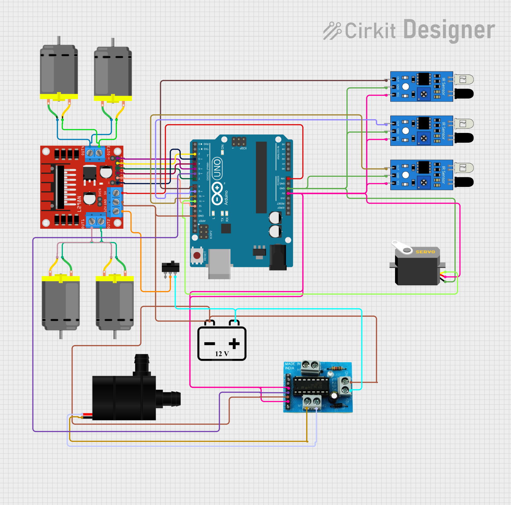
Circuit Documentation
Summary
This circuit is designed to control multiple DC motors, a servo motor, and IR sensors using an Arduino UNO microcontroller. It includes motor drivers for handling the power requirements of the motors and IR sensors for input. A 12V battery powers the system, with a toggle switch to control power flow. The Arduino UNO is the central processing unit, interfacing with the IR sensors, controlling the servo motor, and managing the motor drivers which in turn control the DC motors and a water pump.
Component List
Microcontroller
- Arduino UNO: A microcontroller board based on the ATmega328P. It has digital input/output pins, analog inputs, a USB connection for programming, and power jacks.
Motor Drivers
- L298N DC Motor Driver: A module capable of driving two DC motors or one stepper motor. It provides the necessary current amplification from the Arduino outputs.
- L293D Motor Driver Module: A motor driver capable of driving DC and stepper motors. It has two H-bridge drivers and is suitable for bidirectional control of two DC motors.
Motors
- DC Motor: A simple electric motor that converts electrical energy into mechanical energy. Four of these are included in the circuit.
- Servo: A rotary actuator that allows for precise control of angular position. It is controlled by sending electrical pulses of varying width.
- Water Pump: An electric pump for moving water, powered by the circuit.
Sensors
- IR Sensor: An infrared sensor used for object detection or distance measurement. Three of these are included in the circuit.
Power Supply
- 12V Battery: A battery providing the 12V necessary to power the motors and motor drivers.
Switch
- Toggle Switch: A switch that can connect or disconnect the circuit from the power supply.
Miscellaneous
- Comment: A placeholder for additional notes or comments about the circuit.
Wiring Details
Arduino UNO
- 5V: Powers the L293D Motor Driver Module, IR sensors, and the servo motor.
- GND: Common ground for the Arduino, IR sensors, servo motor, and motor drivers.
- Vin: Connected to the 5V pin of the L298N DC motor driver.
- Digital Pins (D2-D12): Control signals for the L298N DC motor driver, servo motor, and IR sensors.
L298N DC Motor Driver
- 5V: Receives power from the Arduino UNO's Vin pin.
- GND: Connected to the 12V battery's negative terminal and Arduino's GND.
- IN1, IN2, IN3, IN4: Control inputs from the Arduino UNO.
- OUT1, OUT2, OUT3, OUT4: Outputs to the DC motors.
- 12V: Connected to the toggle switch for power control.
L293D Motor Driver Module
- 5V, EN1: Powered by the Arduino UNO's 5V pin.
- GND: Common ground with the Arduino UNO.
- IN1, IN2: Control inputs from the Arduino UNO.
- M1: Output to the water pump.
DC Motors
- Connected to the outputs of the L298N DC motor driver.
Servo
- VCC: Powered by the Arduino UNO's 5V pin.
- GND: Common ground with the Arduino UNO.
- Pulse: Control signal from the Arduino UNO's D11 pin.
IR Sensors
- VCC: Powered by the Arduino UNO's 5V pin.
- GND: Common ground with the Arduino UNO.
- Out: Output signals to the Arduino UNO's digital pins (D8-D10).
Water Pump
- VCC, GND: Powered by the L293D Motor Driver Module.
12V Battery
- +: Connected to the toggle switch and L293D Motor Driver Module's 12V input.
- -: Common ground with the circuit.
Toggle Switch
- COM: Connected to the 12V battery's positive terminal.
- L2: Connected to the L298N DC motor driver's 12V input and L293D Motor Driver Module's 12V input.
Documented Code
Arduino UNO Code (sketch.ino)
void setup() {
  // put your setup code here, to run once:

}

void loop() {
  // put your main code here, to run repeatedly:

}
This code is a template for the Arduino UNO. The setup() function is called once when the microcontroller is reset, and the loop() function is called repeatedly, allowing the microcontroller to change outputs in response to sensor inputs or other conditions. The actual implementation details need to be filled in based on the specific requirements of the circuit's operation.