
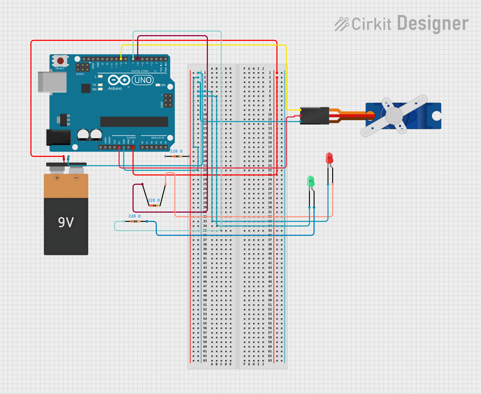
Circuit Documentation
Summary of the Circuit
This circuit is designed to control a set of LEDs and a servo motor using an Arduino UNO microcontroller. The circuit includes a red LED and a green LED, each with a current-limiting resistor, and a Tower Pro SG90 servo motor. The system is powered by a 9V battery, which is stepped down to 5V by the Arduino UNO to power the servo motor. The red and green LEDs are controlled by digital pins on the Arduino, which also sends a control signal to the servo motor. The code for the Arduino is written to simulate a traffic light system with a barrier, where the red LED represents the stop signal and the green LED represents the go signal. The servo motor acts as a barrier that raises and lowers in sync with the LEDs.
Component List
LEDs
- Red LED: A two-pin red LED that lights up when powered.
- Green LED: A two-pin green LED that lights up when powered.
Resistors
- 220 Ohm Resistors: Three resistors each with a resistance of 220 Ohms, used to limit the current through the LEDs.
Microcontroller
- Arduino UNO: A microcontroller board based on the ATmega328P, with a variety of digital and analog I/O pins.
Servo Motor
- Tower Pro SG90 servo: A small and lightweight servo motor capable of precise control.
Power Source
- Battery 9V: A standard 9V battery providing the power source for the circuit.
Wiring Details
Red LED
- Cathode: Connected to the ground (GND) net.
- Anode: Connected to a 220 Ohm resistor, which is then connected to digital pin D6 on the Arduino UNO.
Green LED
- Cathode: Connected to the ground (GND) net.
- Anode: Connected to a 220 Ohm resistor, which is then connected to digital pin D7 on the Arduino UNO.
Resistors
- 220 Ohm Resistors: Each resistor is connected in series with an LED and an Arduino digital pin.
Arduino UNO
- GND: Connected to the ground net, which includes the cathodes of both LEDs, the GND pin of the servo, and the GND terminal of the battery.
- Vin: Connected to the VCC terminal of the 9V battery.
- 5V: Provides power to the +5V pin of the servo motor.
- D6: Controls the red LED through a 220 Ohm resistor.
- D7: Controls the green LED through a 220 Ohm resistor.
- D9: Sends control signals to the servo motor.
Tower Pro SG90 servo
- Signal: Connected to digital pin D9 on the Arduino UNO.
- +5V: Powered by the 5V output from the Arduino UNO.
- GND: Connected to the ground net.
Battery 9V
- VCC: Provides power to the Vin pin of the Arduino UNO.
- GND: Connected to the ground net.
Documented Code
#include <Servo.h>

// Define pins for the LEDs and servo motor
const int redLed = 6;
const int greenLed = 7;
const int servoPin = 9;

Servo myServo;  // Create a Servo object

void setup() {
  // Initialize the LEDs
  pinMode(redLed, OUTPUT);
  pinMode(greenLed, OUTPUT);

  // Attach the servo to pin 9
  myServo.attach(servoPin);

  // Start with the red light on and the barrier raised
  digitalWrite(redLed, HIGH);
  digitalWrite(greenLed, LOW);
  myServo.write(90); // Barrier raised position
}

void loop() {
  // Simulate red light for 5 seconds
  digitalWrite(redLed, HIGH);
  digitalWrite(greenLed, LOW);
  myServo.write(90);  // Keep barrier raised
  delay(5000);  // Wait for 5 seconds

  // Simulate green light for 5 seconds
  digitalWrite(redLed, LOW);
  digitalWrite(greenLed, HIGH);
  myServo.write(0);  // Lower the barrier
  delay(5000);  // Wait for 5 seconds
}
The code above is written for the Arduino UNO and is responsible for controlling the LEDs and servo motor. It sets up the pins, initializes the servo, and then enters a loop where it alternates between the red and green LEDs, simulating a traffic light with a barrier. The servo motor's position is controlled in sync with the LEDs, raising the barrier when the red LED is on and lowering it when the green LED is on.