
Circuit Documentation
Summary
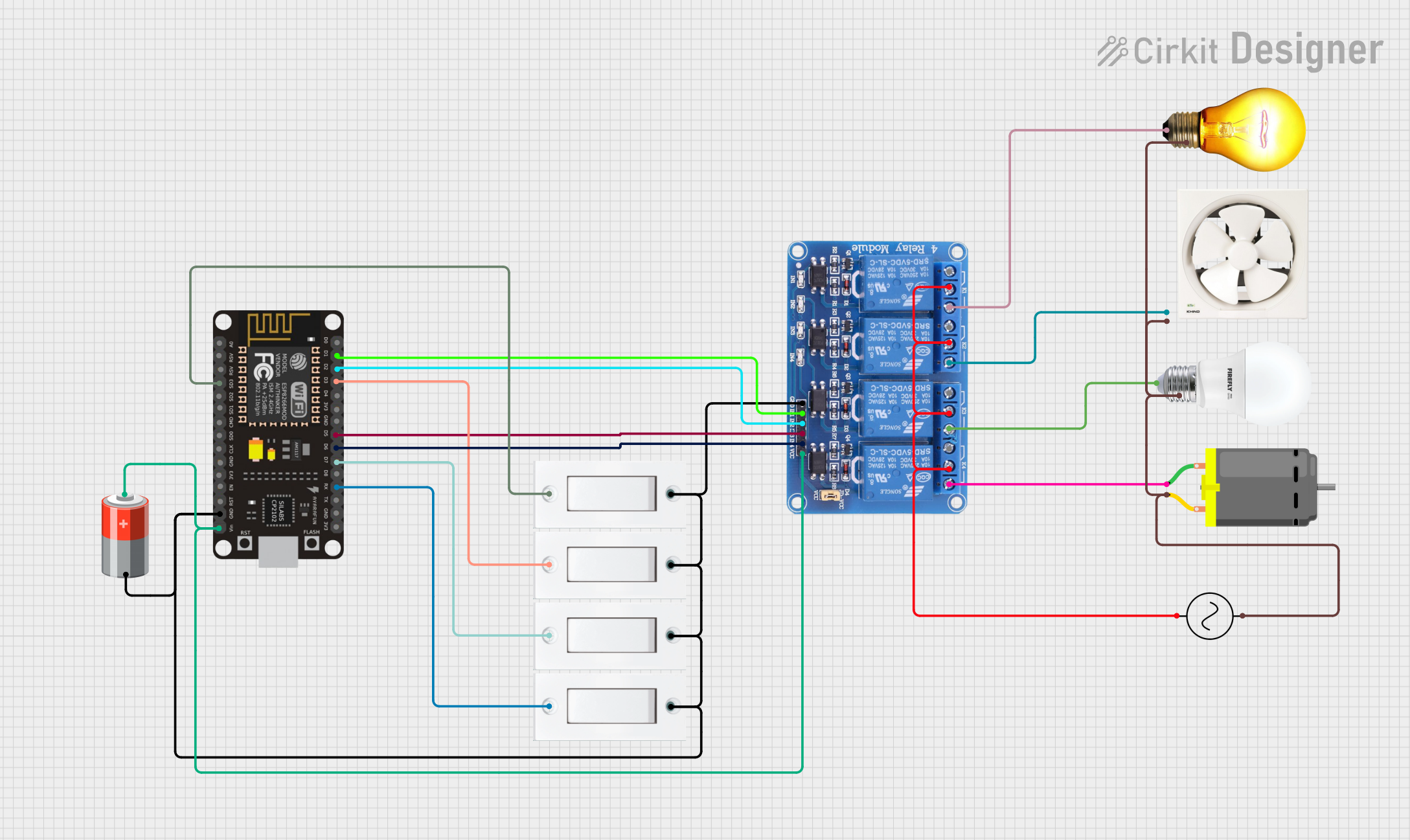
The circuit in question appears to be a control system utilizing an ESP8266 NodeMCU microcontroller to operate a 4-channel relay, which in turn controls various loads including an AC bulb, an exhaust fan, a DC motor, and another bulb. The system is powered by a 5V battery and also interfaces with multiple flush switches. An AC supply is used to power the loads through the relay.
Component List
Relay 4 Channel 5v
- Description: A 4-channel relay module capable of controlling up to four separate high-power circuits.
- Pins: GND, IN1, IN2, IN3, IN4, VCC, COM1, COM2, COM3, COM4, NO1, NO2, NO3, NO4, NC1, NC2, NC3, NC4
Flush Switch
- Description: A simple push-button switch used to provide a digital input to the microcontroller.
- Pins: GND, VCC
AC Supply
- Description: Provides alternating current to power the AC loads in the circuit.
- Pins: +ve, -ve
AC Bulb
- Description: A standard AC-powered light bulb.
- Pins: P, N
DC Motor
- Description: A motor that runs on direct current, controlled by the relay.
- Pins: pin 1, pin 2
ESP8266 NodeMCU
- Description: A microcontroller board with Wi-Fi capabilities.
- Pins: D0, D1, D2, D3, D4, 3V3, GND, D5, D6, D7, D8, RX, TX, A0, RSV, SD3, SD2, SD1, CMD, SD0, CLK, EN, RST, VIN
5v Battery
- Description: Provides the 5V power supply for the circuit.
- Pins: +, -
Exhaust Fan 12"
- Description: A 12-inch exhaust fan controlled by the relay.
- Pins: Live, Neutral
BULB
- Description: An additional bulb controlled by the relay.
- Pins: +, -
Wiring Details
Relay 4 Channel 5v
- GND: Connected to system ground.
- IN1 - IN4: Controlled by ESP8266 NodeMCU pins D1, D2, D5, and D6 respectively.
- VCC: Powered by the 5V battery.
- COM1 - COM4: Connected to the AC supply's +ve.
- NO1 - NO4: Connected to the AC Bulb (P), Exhaust Fan (Live), BULB (+), and DC Motor (pin 1) respectively.
Flush Switches
- GND: Connected to system ground.
- VCC: Controlled by ESP8266 NodeMCU pins D3, D7, RX, and SD3.
AC Supply
- +ve: Connected to COM pins of the relay.
- -ve: Connected to system ground.
AC Bulb
- P: Connected to NO1 of the relay.
- N: Connected to system ground.
DC Motor
- pin 1: Connected to NO4 of the relay.
- pin 2: Connected to system ground.
ESP8266 NodeMCU
- D1, D2, D3, D5, D6, D7, RX, SD3: Control signals for relay and flush switches.
- GND: Connected to system ground.
- VIN: Powered by the 5V battery.
5v Battery
- +: Powers the VCC of the relay and VIN of the ESP8266 NodeMCU.
- -: Connected to system ground.
Exhaust Fan 12"
- Live: Connected to NO2 of the relay.
- Neutral: Connected to system ground.
BULB
- +: Connected to NO3 of the relay.
- -: Connected to system ground.
Documented Code
No code was provided for the ESP8266 NodeMCU. The expected code would handle the logic for reading the state of the flush switches and controlling the relay channels accordingly. It would also include setup for Wi-Fi connectivity if remote control is desired.