
Arduino Mega 2560 Controlled Robotic System with DC Motors, Servos, and IR Sensors
View and Edit Project In Cirkit Designer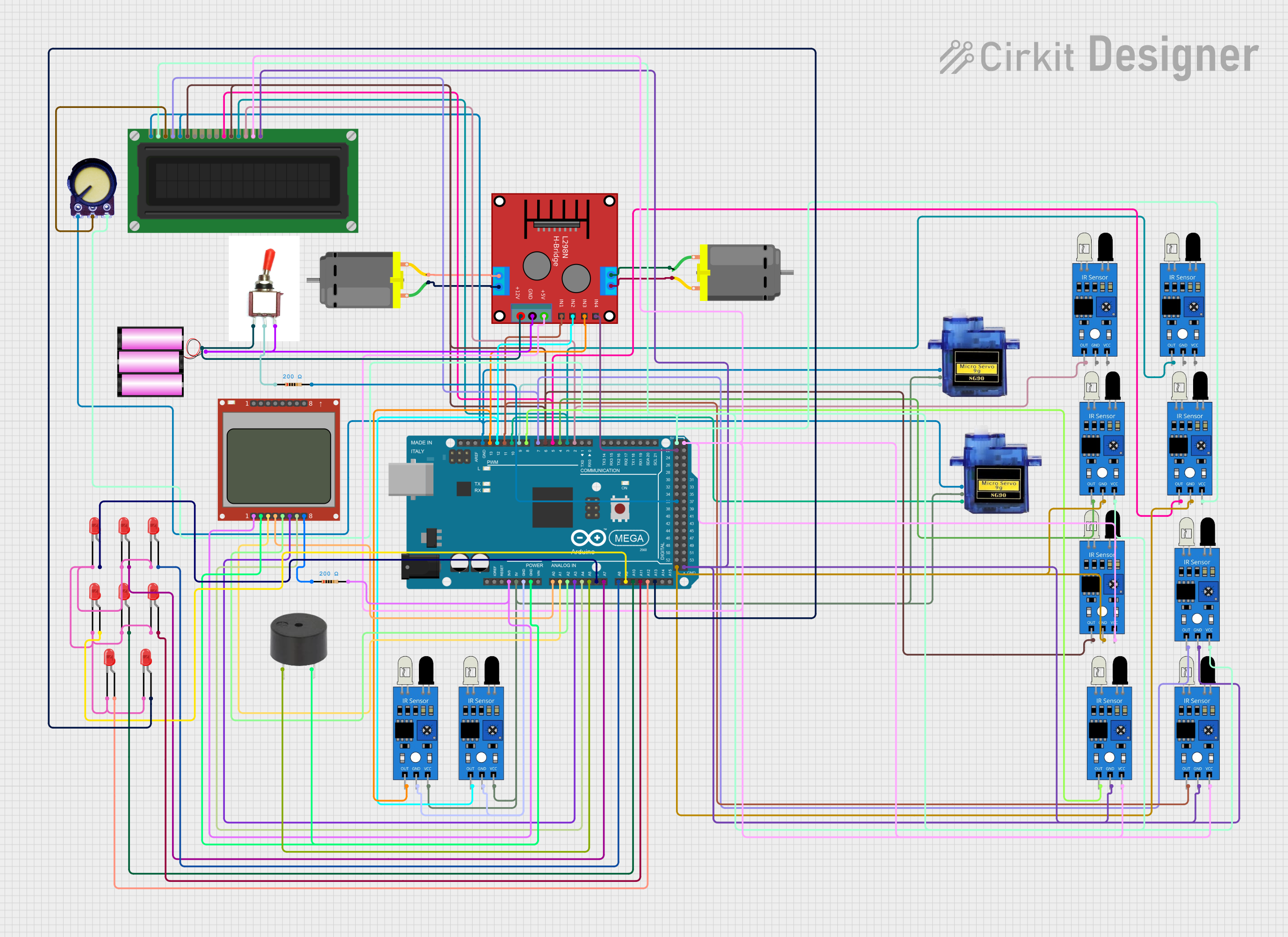
Circuit Documentation
Summary
This document provides a detailed overview of a circuit that includes various components such as DC motors, micro servos, an Arduino Mega 2560, an H-bridge, an LCD display, IR sensors, a potentiometer, a battery, a toggle switch, resistors, a buzzer, and LEDs. The circuit is designed to control motors and servos, read sensor inputs, and display information on an LCD screen. The Arduino Mega 2560 microcontroller is used to manage the operations of the circuit.
Component List
DC Motor
- Pins: pin 1, pin 2
- Description: A motor that runs on direct current (DC).
Micro Servo 9G
- Pins: GND, +5V, PWM
- Description: A small servo motor used for precise control of angular position.
Arduino Mega 2560
- Pins: IOREF, RESET, 3V3, 5V, GND, VIN, A0-A15, D0-D53, PWM pins, AREF, SDA, SCL
- Description: A microcontroller board based on the ATmega2560.
H-Bridge (Ponte H)
- Pins: OUT4-Motor2, OUT3-Motor2, OUT2-Motor1, OUT1-Motor1, 5V, GND, 12V, IN3, IN1, IN2, IN4
- Description: A motor driver that allows control of the direction and speed of motors.
Nokia 5110 LCD
- Pins: DN(MOSI), D/C, RST, SCE, GND, VCC, LED, SCLK
- Description: A graphical LCD display.
IR Sensor
- Pins: out, gnd, vcc
- Description: An infrared sensor used for detecting objects.
LCD Display (16 pin)
- Pins: VSS, VDD, VO, RS, R_W, E, DB0-DB7, A, K
- Description: A 16-pin LCD display.
Potentiometer
- Pins: GND, Output, VCC
- Description: A variable resistor used to adjust voltage levels.
Battery 12V
- Pins: +, -
- Description: A 12V battery used to power the circuit.
Toggle Switch
- Pins: Vcc, Sig, Gnd
- Description: A switch used to control the flow of electricity.
Resistor
- Pins: pin1, pin2
- Description: A 200 Ohms resistor used to limit current.
Buzzer
- Pins: PIN, GND
- Description: A device that produces sound.
LED: Two Pin (red)
- Pins: cathode, anode
- Description: A red LED used for indication.
Wiring Details
DC Motor 1
- pin 1 connected to H-Bridge OUT1-Motor1
- pin 2 connected to H-Bridge OUT2-Motor1
DC Motor 2
- pin 1 connected to H-Bridge OUT4-Motor2
- pin 2 connected to H-Bridge OUT3-Motor2
Micro Servo 9G 1
- GND connected to Arduino Mega 2560 GND
- +5V connected to Arduino Mega 2560 5V
- PWM connected to Arduino Mega 2560 D9 PWM
Micro Servo 9G 2
- GND connected to Arduino Mega 2560 GND
- +5V connected to Arduino Mega 2560 5V
- PWM connected to Arduino Mega 2560 D10 PWM
Arduino Mega 2560
- GND connected to Micro Servo 9G GND, Potentiometer GND, LCD Display (16 pin) VSS, LCD Display (16 pin) R_W, H-Bridge GND, IR Sensor GND, Buzzer GND, Nokia 5110 LCD GND
- 5V connected to Micro Servo 9G +5V, IR Sensor VCC, LCD Display (16 pin) VDD, Potentiometer VCC, H-Bridge 5V
- 3V3 connected to Resistor pin2, Nokia 5110 LCD VCC
- A0 connected to Nokia 5110 LCD RST
- A1 connected to Nokia 5110 LCD SCE
- A2 connected to Nokia 5110 LCD D/C
- A3 connected to Nokia 5110 LCD DN(MOSI)
- A4 connected to Nokia 5110 LCD SCLK
- A5 connected to Buzzer PIN
- A6 connected to LED anode
- A7 connected to LED anode
- A8 connected to LED anode
- A9 connected to LED anode
- A10 connected to LED anode
- A11 connected to LED anode
- A12 connected to LED anode
- A13 connected to LED anode
- D2 PWM connected to IR Sensor out, LCD Display (16 pin) DB7
- D3 PWM connected to IR Sensor out, LCD Display (16 pin) DB6
- D4 PWM connected to IR Sensor out
- D5 PWM connected to IR Sensor out, LCD Display (16 pin) DB4
- D6 PWM connected to IR Sensor out, LCD Display (16 pin) DB5, LCD Display (16 pin) E
- D7 PWM connected to IR Sensor out, LCD Display (16 pin) RS
- D8 PWM connected to IR Sensor out
- D11 PWM connected to H-Bridge IN1, IR Sensor out
- D12 PWM connected to H-Bridge IN2, IR Sensor out
- D13 PWM connected to H-Bridge IN3, IR Sensor out
- D22 connected to H-Bridge IN4
- D36 connected to Resistor pin2
H-Bridge (Ponte H)
- OUT1-Motor1 connected to DC Motor pin 1
- OUT2-Motor1 connected to DC Motor pin 2
- OUT3-Motor2 connected to DC Motor pin 2
- OUT4-Motor2 connected to DC Motor pin 1
- 5V connected to Arduino Mega 2560 5V
- GND connected to Arduino Mega 2560 GND
- 12V connected to Battery 12V +
- IN1 connected to Arduino Mega 2560 D11 PWM
- IN2 connected to Arduino Mega 2560 D12 PWM
- IN3 connected to Arduino Mega 2560 D13 PWM
- IN4 connected to Arduino Mega 2560 D22
Nokia 5110 LCD
- VCC connected to Arduino Mega 2560 3V3
- GND connected to Arduino Mega 2560 GND
- RST connected to Arduino Mega 2560 A0
- SCE connected to Arduino Mega 2560 A1
- D/C connected to Arduino Mega 2560 A2
- DN(MOSI) connected to Arduino Mega 2560 A3
- SCLK connected to Arduino Mega 2560 A4
- LED connected to Resistor pin1
IR Sensor
- out connected to Arduino Mega 2560 D2 PWM, D3 PWM, D4 PWM, D5 PWM, D6 PWM, D7 PWM, D8 PWM, D11 PWM, D12 PWM, D13 PWM
- gnd connected to Arduino Mega 2560 GND
- vcc connected to Arduino Mega 2560 5V
LCD Display (16 pin)
- VSS connected to Arduino Mega 2560 GND
- VDD connected to Arduino Mega 2560 5V
- VO connected to Potentiometer Output
- RS connected to Arduino Mega 2560 D7 PWM
- R_W connected to Arduino Mega 2560 GND
- E connected to Arduino Mega 2560 D6 PWM
- DB0-DB3 not connected
- DB4 connected to Arduino Mega 2560 D5 PWM
- DB5 connected to Arduino Mega 2560 D6 PWM
- **