
Lilygo 7670e-Based Smart Interface with LCD Display and Keypad
View and Edit Project In Cirkit Designer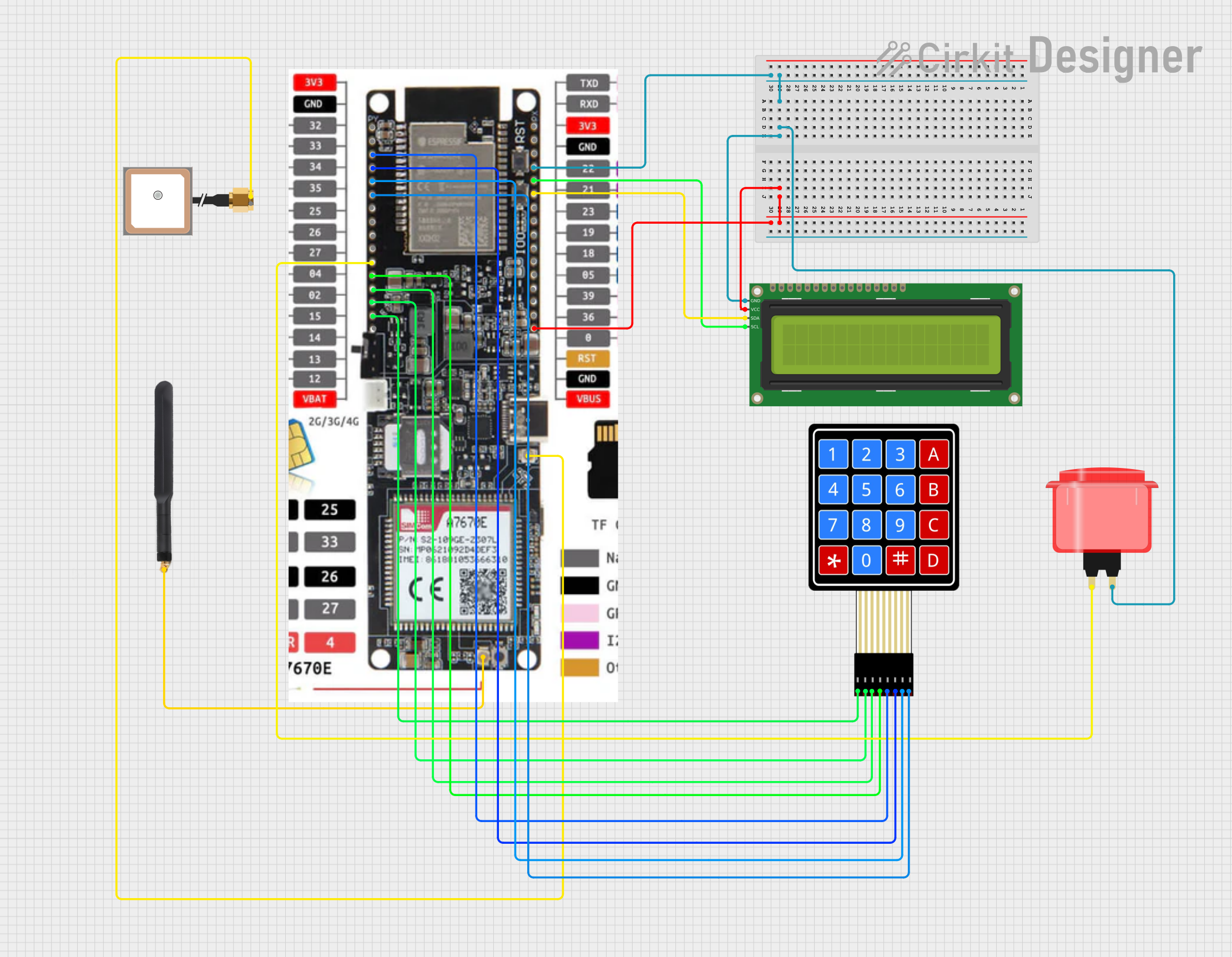
Circuit Documentation
Summary
This document provides a detailed overview of a circuit design that includes various components such as an arcade button, an I2C LCD, a 4G antenna, a GPS antenna, a membrane matrix keypad, and a Lilygo 7670e microcontroller. The document includes a component list, wiring details, and code documentation.
Component List
Arcade Button (red)
- Description: A simple push-button switch.
- Pins: 1 pin (no name yet)
- Purpose in Circuit: Used as an input device to trigger actions in the microcontroller.
16x2 I2C LCD
- Description: A 16x2 character LCD display with I2C interface.
- Pins: GND, VCC, SDA, SCL
- Purpose in Circuit: Used to display information.
4G Antenna
- Description: An antenna for 4G communication.
- Pins: Connection
- Purpose in Circuit: Used for 4G connectivity.
Antenna GPS Embedded SMA
- Description: An embedded GPS antenna with SMA connector.
- Pins: VCC, GND
- Purpose in Circuit: Used for GPS signal reception.
4X4 Membrane Matrix Keypad
- Description: A 4x4 matrix keypad.
- Pins: R1, R2, R3, R4, C1, C2, C3, C4
- Purpose in Circuit: Used as an input device for entering data.
Lilygo 7670e
- Description: A microcontroller with various I/O pins.
- Pins: 3v3, Gnd, Pin 32, pin 33, pin 34, pin35, pin 25, Pin 26, Pin 27, Pin 4, Pin 2, Pin 15, pin 14, Pin 13, Pin 12, VBAT, TXD, RXD, 3v3, Pin 22, Pin 21, Pin 23, Pin 19, Pin 18, Pin 5, Pin 39, Pin 36, Pin 0, RST, VBUS, LTE antenna, Gps Antenna, Type C
- Purpose in Circuit: Acts as the main processing unit, controlling other components and handling data processing.
Wiring Details
Arcade Button (red)
- Pin (no name yet):
- Connected to Lilygo 7670e Pin 2
- Connected to 16x2 I2C LCD GND
- Connected to Lilygo 7670e Gnd
16x2 I2C LCD
GND:
- Connected to Arcade Button (red) pin (no name yet)
- Connected to Lilygo 7670e Gnd
VCC:
- Connected to Lilygo 7670e VBUS
SDA:
- Connected to Lilygo 7670e Pin 21
SCL:
- Connected to Lilygo 7670e Pin 22
4G Antenna
- Connection:
- Connected to Lilygo 7670e LTE antenna
Antenna GPS Embedded SMA
VCC:
- Connected to Lilygo 7670e Gps Antenna
GND:
- No connection specified
4X4 Membrane Matrix Keypad
C1:
- Connected to Lilygo 7670e Pin 32
C2:
- Connected to Lilygo 7670e pin 33
C3:
- Connected to Lilygo 7670e pin 34
C4:
- Connected to Lilygo 7670e pin35
R1:
- Connected to Lilygo 7670e Pin 12
R2:
- Connected to Lilygo 7670e Pin 13
R3:
- Connected to Lilygo 7670e pin 14
R4:
- Connected to Lilygo 7670e Pin 15
Lilygo 7670e
Gnd:
- Connected to Arcade Button (red) pin (no name yet)
- Connected to 16x2 I2C LCD GND
VBUS:
- Connected to 16x2 I2C LCD VCC
Pin 2:
- Connected to Arcade Button (red) pin (no name yet)
Pin 12:
- Connected to 4X4 Membrane Matrix Keypad R1
Pin 13:
- Connected to 4X4 Membrane Matrix Keypad R2
pin 14:
- Connected to 4X4 Membrane Matrix Keypad R3
Pin 15:
- Connected to 4X4 Membrane Matrix Keypad R4
Pin 21:
- Connected to 16x2 I2C LCD SDA
Pin 22:
- Connected to 16x2 I2C LCD SCL
Pin 32:
- Connected to 4X4 Membrane Matrix Keypad C1
pin 33:
- Connected to 4X4 Membrane Matrix Keypad C2
pin 34:
- Connected to 4X4 Membrane Matrix Keypad C3
pin35:
- Connected to 4X4 Membrane Matrix Keypad C4
LTE antenna:
- Connected to 4G Antenna Connection
Gps Antenna:
- Connected to Antenna GPS Embedded SMA VCC
Code Documentation
No code is provided for this circuit.
This document provides a comprehensive overview of the circuit design, including the components used, their connections, and their purposes. This should serve as a useful reference for understanding and troubleshooting the circuit.