
Arduino 101 Based Touch-Controlled LED Matrix with DHT22 Sensor Integration
View and Edit Project In Cirkit Designer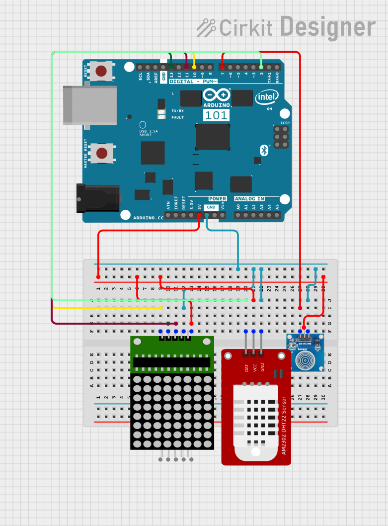
Circuit Documentation
Summary
The circuit in question is designed to interface an Arduino 101 microcontroller with a touch sensor, an 8x8 LED matrix, and a DHT22 temperature and humidity sensor. The Arduino 101 serves as the central processing unit, controlling the data flow and interactions between the sensors and the display. The touch sensor provides a user interface, the DHT22 sensor measures environmental conditions, and the 8x8 LED matrix displays information or patterns as programmed.
Component List
Arduino 101
- Description: A microcontroller board based on the Intel Curie Module, designed for building IoT projects.
- Pins: A5/SCL, A4/SDA, AREF, GND, D13/SCK, D12/MISO, D11 PWM/MOSI, D10 PWM/SS, D9 PWM, D8, D7, D6 PWM, D5 PWM, D4, D3 PWM, D2, D1/TX, D0/RX, AIN, ioref, RESET, 3V3, 5V, VIN, A0, A1, A2, A3, ICSP MISO, ICSP SCK, ICSP MOSI.
Touch Sensor
- Description: A capacitive touch sensor module used for human interface input.
- Pins: IO, VCC, GND.
8x8 LED Matrix
- Description: A matrix of 64 LEDs arranged in an 8x8 grid, used for displaying characters or graphics.
- Pins: VCC, DIN, CLK, CS, GND.
DHT22 Sensor
- Description: A sensor used for measuring temperature and humidity.
- Pins: GND, VCC, DAT.
Wiring Details
Arduino 101
- 5V connected to 8x8 LED Matrix VCC, DHT22 VCC, and Touch Sensor VCC.
- GND connected to 8x8 LED Matrix GND, DHT22 GND, and Touch Sensor GND.
- D10 PWM/SS connected to 8x8 LED Matrix CS.
- D13/SCK connected to 8x8 LED Matrix CLK.
- D11 PWM/MOSI connected to 8x8 LED Matrix DIN.
- D2 connected to DHT22 DAT.
- D7 connected to Touch Sensor IO.
Touch Sensor
- VCC connected to Arduino 101 5V.
- GND connected to Arduino 101 GND.
- IO connected to Arduino 101 D7.
8x8 LED Matrix
- VCC connected to Arduino 101 5V.
- DIN connected to Arduino 101 D11 PWM/MOSI.
- CLK connected to Arduino 101 D13/SCK.
- CS connected to Arduino 101 D10 PWM/SS.
- GND connected to Arduino 101 GND.
DHT22 Sensor
- VCC connected to Arduino 101 5V.
- GND connected to Arduino 101 GND.
- DAT connected to Arduino 101 D2.
Documented Code
Since no code was provided in the input, this section cannot be completed. However, typically this section would include the source code for the microcontroller, along with comments explaining the functionality of each part of the code. This would cover initializations, main loop, interrupt service routines, and any functions for handling sensor data or controlling the LED matrix.