
ESP32-Controlled LED Matrix with 16-Channel Multiplexers and RS485 Communication
View and Edit Project In Cirkit Designer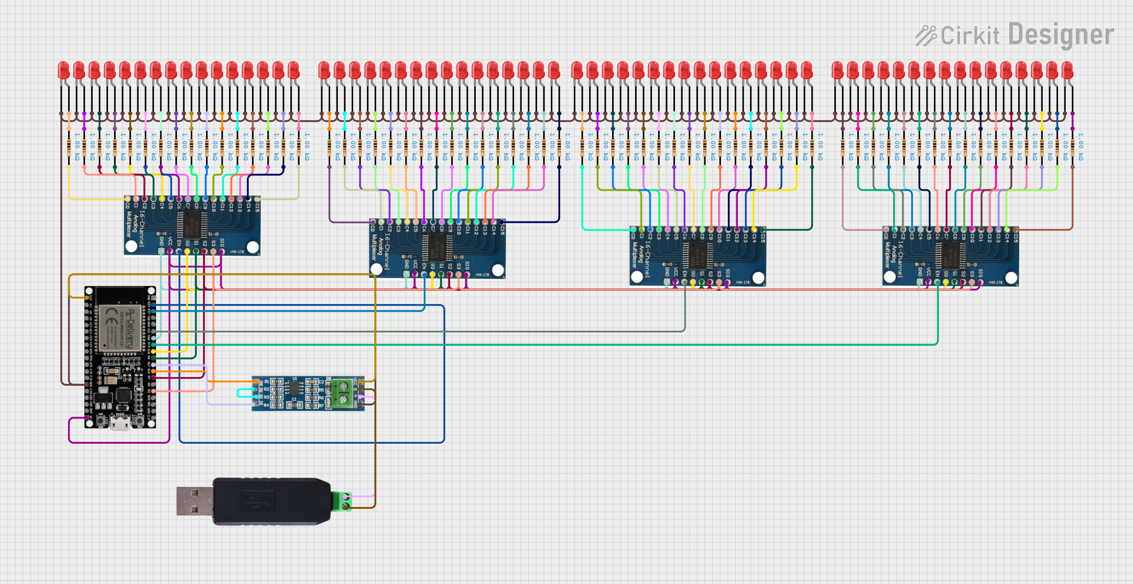
Circuit Documentation
Summary
This circuit is designed to control LEDs connected to four 16-channel analog multiplexers using an ESP32 microcontroller. The ESP32 receives commands via an RS485 module to turn on specific LEDs. The command format is a single byte where the upper 2 bits represent the multiplexer index (0-3) and the lower 4 bits represent the LED index (0-15).
Component List
16 Channel Analog Multiplexer Bob
- Description: A multiplexer used to control multiple LEDs.
- Pins: GND, VCC, EN, S0, S1, S2, S3, SIG, C0, C1, C2, C3, C4, C5, C6, C7, C8, C9, C10, C11, C12, C13, C14, C15
ESP32 38 PINS
- Description: A microcontroller used to control the multiplexers and communicate via RS485.
- Pins: GND, G23, G22, TXD, RXD, G21, G19, G18, G5, G17, G16, G4, G0, G2, G15, SDI, SD0, CLK, 3V3, EN, SP, SN, G34, G35, G32, 33, G25, G26, G27, G14, G12, G13, SD2, SD3, 5V
Resistor
- Description: A resistor used to limit current to the LEDs.
- Pins: pin1, pin2
- Properties: Resistance: 1000 Ohms
LED: Two Pin (red)
- Description: A red LED.
- Pins: cathode, anode
RS-485 Module
- Description: A module used for RS485 communication.
- Pins: VCC, B, A, GND, RO, RE, DE, DI
RS485 to USB Converter
- Description: A converter used to interface RS485 with USB.
- Pins: A/TX, B/RX
Wiring Details
16 Channel Analog Multiplexer Bob
- GND: Connected to GND of ESP32.
- VCC: Connected to 5V of ESP32.
- EN: Connected to G23, G22, G21, and G19 of ESP32.
- S0: Connected to G18 of ESP32.
- S1: Connected to G5 of ESP32.
- S2: Connected to G4 of ESP32.
- S3: Connected to G2 of ESP32.
- SIG: Connected to VCC.
- C0 to C15: Connected to pin2 of respective resistors.
ESP32 38 PINS
- GND: Connected to GND of all multiplexers and RS-485 module.
- 5V: Connected to VCC of all multiplexers.
- G23, G22, G21, G19: Connected to EN pins of respective multiplexers.
- G18: Connected to S0 of all multiplexers.
- G5: Connected to S1 of all multiplexers.
- G4: Connected to S2 of all multiplexers.
- G2: Connected to S3 of all multiplexers.
- G17: Connected to DI of RS-485 module.
- G16: Connected to RO of RS-485 module.
- 3V3: Connected to VCC of RS-485 module.
Resistor
- pin1: Connected to anode of respective LEDs.
- pin2: Connected to C0 to C15 of respective multiplexers.
LED: Two Pin (red)
- cathode: Connected to GND.
- anode: Connected to pin1 of respective resistors.
RS-485 Module
- VCC: Connected to 3V3 of ESP32.
- B: Connected to B/RX of RS485 to USB Converter.
- A: Connected to A/TX of RS485 to USB Converter.
- GND: Connected to GND of ESP32.
- RO: Connected to G16 of ESP32.
- RE: Connected to DE of RS-485 module.
- DE: Connected to RE of RS-485 module.
- DI: Connected to G17 of ESP32.
RS485 to USB Converter
- B/RX: Connected to B of RS-485 module.
- A/TX: Connected to A of RS-485 module.
Code Documentation
/*
 * This Arduino Sketch controls LEDs connected to four 16-channel analog
 * multiplexers using an ESP32 microcontroller. The ESP32 receives commands
 * via an RS485 module to turn on specific LEDs. The command format is a
 * single byte where the upper 2 bits represent the multiplexer index (0-3)
 * and the lower 4 bits represent the LED index (0-15).
 */

// Multiplexer control pins
const int enPins[4] = {23, 22, 21, 19};
const int s0Pin = 18;
const int s1Pin = 5;
const int s2Pin = 4;
const int s3Pin = 2;

#define Rflag 15
#define RXD2 16
#define TXD2 17

void setup() {
  // Initialize serial communication for RS485
  Serial.begin(9600);
  Serial2.begin(9600, SERIAL_8N1, RXD2, TXD2);

  // Initialize multiplexer control pins
  for (int i = 0; i < 4; i++) {
    pinMode(enPins[i], OUTPUT);
    digitalWrite(enPins[i], HIGH); // Disable all multiplexers initially
  }
  pinMode(s0Pin, OUTPUT);
  pinMode(s1Pin, OUTPUT);
  pinMode(s2Pin, OUTPUT);
  pinMode(s3Pin, OUTPUT);
  pinMode(Rflag, OUTPUT);
  digitalWrite(Rflag, LOW);
}

void loop() {
  if (Serial2.available()) {
    int command = Serial2.read();
    Serial.print("command:");
    Serial.println(command, BIN);
    int muxIndex = (command >> 4) & 0x03; // Extract multiplexer index (0-3)
    Serial.print("muxIndex:");
    Serial.println(muxIndex, BIN);
    int ledIndex = command & 0x0F; // Extract LED index (0-15)
    Serial.print("ledIndex:");
    Serial.println(ledIndex, BIN);

    if (bitRead(command, 6) == 1){
      // Set multiplexer address
      digitalWrite(s0Pin, ledIndex & 0x01);
      digitalWrite(s1Pin, (ledIndex >> 1) & 0x01);
      digitalWrite(s2Pin, (ledIndex >> 2) & 0x01);
      digitalWrite(s3Pin, (ledIndex >> 3) & 0x01);

      // Enable the selected multiplexer
      for (int i = 0; i < 4; i++) {
        digitalWrite(enPins[i], i == muxIndex ? LOW : HIGH);
      }
    } else {
      for (int i = 0; i < 4; i++) {
        digitalWrite(enPins[i], HIGH); // Disable all multiplexers initially
      }
    }
  }
}
This code initializes the ESP32 microcontroller to control the multiplexers and LEDs. It sets up the serial communication for RS485 and configures the multiplexer control pins. In the main loop, it reads commands from the RS485 module and controls the multiplexers and LEDs accordingly.