Cirkit Designer
Your all-in-one circuit design IDE
Home /
Project Documentation
Arduino Nano Wireless Joystick Controller with NRF24L01
Circuit Documentation
Summary
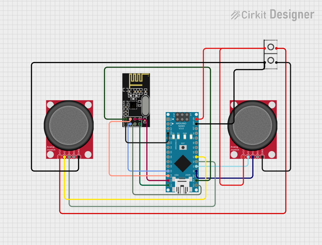
This document provides a detailed overview of a circuit that includes an Arduino Nano, an NRF24L01 wireless module, and two analog joysticks. The circuit is designed to interface the joysticks with the Arduino Nano, which in turn communicates with the NRF24L01 module for wireless data transmission. The document includes a component list, wiring details, and the embedded code used in the microcontroller.
Component List
Arduino Nano
- Description: A small, complete, and breadboard-friendly board based on the ATmega328P.
- Pins: D1/TX, D0/RX, RESET, GND, D2, D3, D4, D5, D6, D7, D8, D9, D10, D11/MOSI, D12/MISO, VIN, 5V, A7, A6, A5, A4, A3, A2, A1, A0, AREF, 3V3, D13/SCK
NRF24L01
- Description: A wireless transceiver module for low-power, high-speed communication.
- Pins: IRQ (not used), MOSI, CSN, VCC (3V), GND, CE, SCK, MISO
Analog Joystick (Wokwi Compatible)
- Description: An analog joystick module compatible with Wokwi simulation.
- Pins: VCC, VERT, HORZ, SEL, GND
Wire Connector
- Description: A simple wire connector for power distribution.
- Pins: +, -
Wiring Details
Arduino Nano
- GND is connected to GND of the NRF24L01.
- D9 is connected to CE of the NRF24L01.
- D10 is connected to CSN of the NRF24L01.
- D11/MOSI is connected to MOSI of the NRF24L01.
- D12/MISO is connected to MISO of the NRF24L01.
- VIN is connected to VCC of the first Analog Joystick and the wire connector.
- GND is connected to GND of the second Analog Joystick and the wire connector.
- A3 is connected to VERT of the second Analog Joystick.
- A2 is connected to HORZ of the second Analog Joystick.
- A1 is connected to VERT of the first Analog Joystick.
- A0 is connected to HORZ of the first Analog Joystick.
- 3V3 is connected to VCC (3V) of the NRF24L01.
- D13/SCK is connected to SCK of the NRF24L01.
NRF24L01
- GND is connected to GND of the Arduino Nano.
- CE is connected to D9 of the Arduino Nano.
- CSN is connected to D10 of the Arduino Nano.
- MOSI is connected to D11/MOSI of the Arduino Nano.
- MISO is connected to D12/MISO of the Arduino Nano.
- VCC (3V) is connected to 3V3 of the Arduino Nano.
- SCK is connected to D13/SCK of the Arduino Nano.
Analog Joystick (First)
- VCC is connected to VIN of the Arduino Nano and the wire connector.
- VERT is connected to A1 of the Arduino Nano.
- HORZ is connected to A0 of the Arduino Nano.
- GND is connected to - of the wire connector.
Analog Joystick (Second)
- VCC is connected to + of the wire connector.
- VERT is connected to A3 of the Arduino Nano.
- HORZ is connected to A2 of the Arduino Nano.
- GND is connected to - of the wire connector and GND of the Arduino Nano.
Wire Connector
- + is connected to VCC of both Analog Joysticks and VIN of the Arduino Nano.
- - is connected to GND of both Analog Joysticks and GND of the Arduino Nano.
Code Documentation
Arduino Nano Code
sketch.ino
void setup() {
  // put your setup code here, to run once:

}

void loop() {
  // put your main code here, to run repeatedly:

}
documentation.txt
This document provides a comprehensive overview of the circuit, including the components used, their wiring connections, and the embedded code. This should serve as a useful reference for understanding and replicating the circuit.