Arduino Uno R3 Automated Distance Sensing Fan Controller with LCD Feedback
Circuit Documentation
Summary of the Circuit
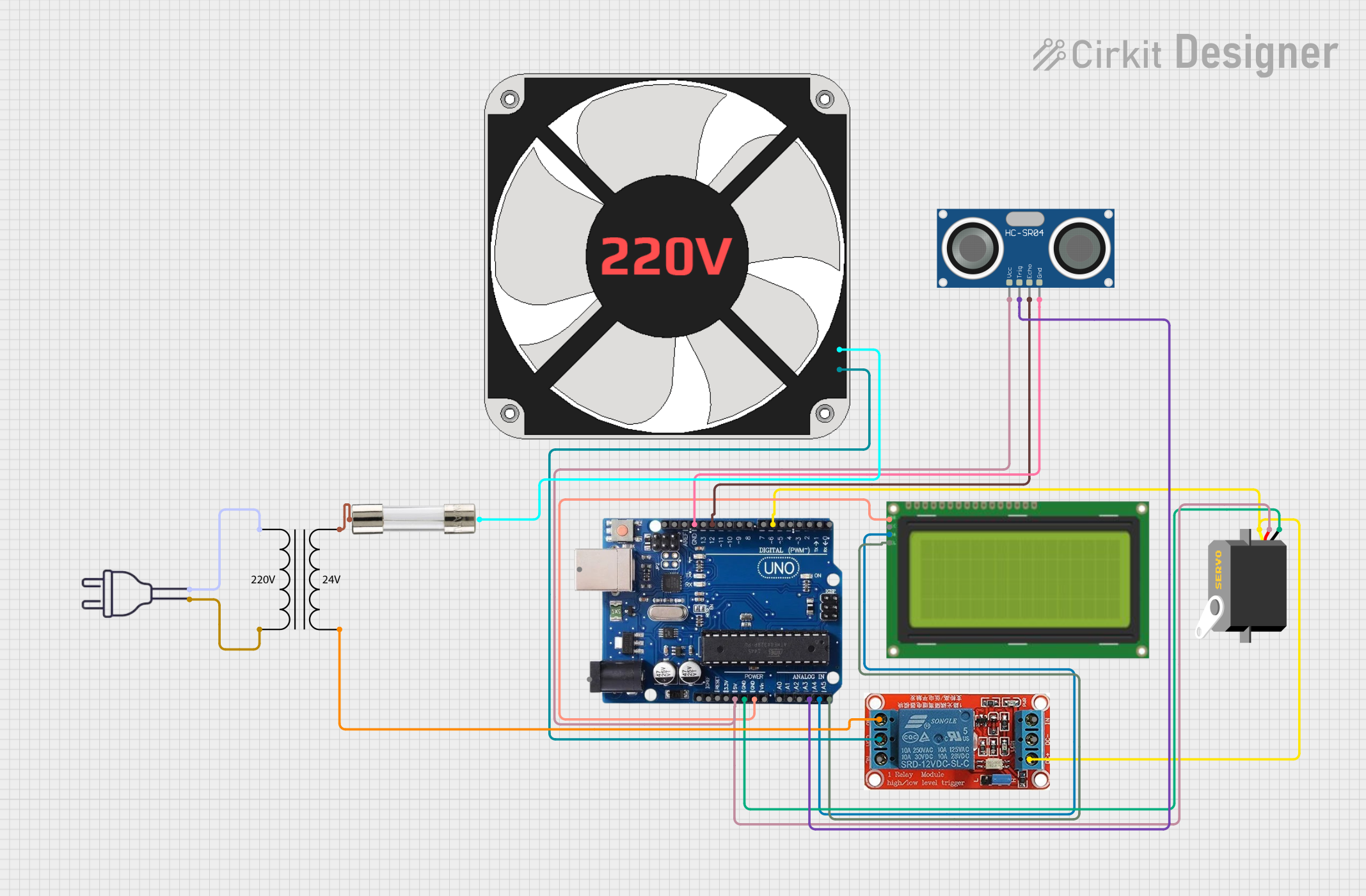
This circuit is designed to interface an Arduino Uno R3 with a servo motor, an HC-SR04 ultrasonic sensor, a 20x4 LCD with I2C interface, a 220V fan, a power transformer (220V to 24V), a 12V relay, and a fuse for safety. The Arduino Uno R3 acts as the central controller, managing the servo motor and ultrasonic sensor, as well as communicating with the LCD for display purposes. The power transformer steps down the 220V mains voltage to 24V, which is then used to control the 220V fan via the 12V relay. The fuse is included for overcurrent protection.
Component List
Arduino Uno R3
- Microcontroller board based on the ATmega328P
- Features digital I/O pins, analog input pins, a USB connection for programming, and power management capabilities.
Servo
- An actuator that can be precisely controlled for angular position.
HC-SR04 Ultrasonic Sensor
- A sensor that measures distance by emitting ultrasonic waves and timing their return after reflecting off an object.
220V Fan
- An electromechanical device that moves air for cooling or ventilation purposes.
LCD 20x4 with I2C Interface
- A liquid crystal display capable of showing 4 lines of 20 characters each, with an I2C interface for communication.
Power Transformer (220V to 24V)
- A device that steps down the voltage from 220V to 24V.
12V Relay
- An electrically operated switch that allows a low-power signal to control a higher power circuit, in this case, the 220V fan.
Fuse
- A safety device that protects the circuit from overcurrent by breaking the connection if the current exceeds a certain threshold.
Power 220V
- The main power supply for the circuit, providing 220V AC.
Wiring Details
Arduino Uno R3
- 5V: Connected to the VCC of the Servo and HC-SR04 Ultrasonic Sensor.
- GND: Common ground for the Servo, HC-SR04 Ultrasonic Sensor, and LCD 20x4 I2C.
- A3: Connected to the TRIG pin of the HC-SR04 Ultrasonic Sensor.
- A4/SDA: Connected to the SCA pin of the LCD 20x4 I2C.
- A5/SCL: Connected to the SCL pin of the LCD 20x4 I2C.
- Pin 12: Connected to the ECHO pin of the HC-SR04 Ultrasonic Sensor.
- Pin 6: Connected to the pulse pin of the Servo and DC+ of the 12V Relay.
Servo
- VCC: Connected to the 5V output of the Arduino Uno R3.
- GND: Connected to the common ground on the Arduino Uno R3.
- Pulse: Connected to pin 6 on the Arduino Uno R3.
HC-SR04 Ultrasonic Sensor
- VCC: Connected to the 5V output of the Arduino Uno R3.
- TRIG: Connected to pin A3 on the Arduino Uno R3.
- ECHO: Connected to pin 12 on the Arduino Uno R3.
- GND: Connected to the common ground on the Arduino Uno R3.
220V Fan
- N: Connected to the COM pin of the 12V Relay.
- L: Connected to Terminal 2 of the Fuse.
LCD 20x4 I2C
- GND: Connected to the common ground on the Arduino Uno R3.
- 5V: Connected to the 5V output of the Arduino Uno R3.
- SCA: Connected to the A4/SDA pin on the Arduino Uno R3.
- SCL: Connected to the A5/SCL pin on the Arduino Uno R3.
Power Transformer (220V to 24V)
- 2 - Primary: Connected to the hot wire of the power 220V.
- 1 - Primary: Connected to the neutral wire of the power 220V.
- 3 - Secondary: Connected to Terminal 1 of the Fuse.
- 4 - Secondary: Connected to the NO pin of the 12V Relay.
12V Relay
- NO: Connected to the 4 - Secondary pin of the Power Transformer (220V to 24V).
- COM: Connected to the N pin of the 220V Fan.
- DC+: Connected to pin 6 on the Arduino Uno R3.
Fuse
- Terminal 1: Connected to the 3 - Secondary pin of the Power Transformer (220V to 24V).
- Terminal 2: Connected to the L pin of the 220V Fan.
Power 220V
- Hot wire: Connected to the 2 - Primary pin of the Power Transformer (220V to 24V).
- Neutral wire: Connected to the 1 - Primary pin of the Power Transformer (220V to 24V).
Documented Code
Arduino Uno R3 - sketch.ino
void setup() {
  // put your setup code here, to run once:

}

void loop() {
  // put your main code here, to run repeatedly:

}
The provided code is a template with empty setup() and loop() functions. The setup() function is intended for initialization code that runs once at the start, while the loop() function contains code that runs repeatedly. Actual implementation details need to be added based on the specific requirements of the circuit's operation.