Arduino UNO Light-Dependent Servo Control System
Circuit Documentation
Summary
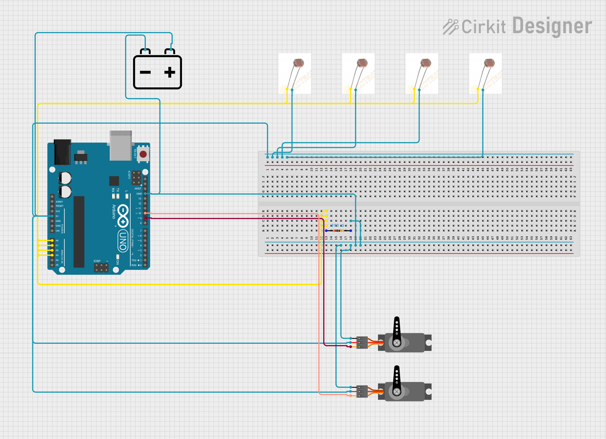
This circuit involves an Arduino UNO microcontroller, multiple Light Dependent Resistors (LDRs), resistors, servos, and a 12V battery. The circuit is designed to read light intensity using LDRs and control servos based on the readings. The Arduino UNO serves as the central controller, processing the input from the LDRs and driving the servos accordingly.
Component List
LDR (Light Dependent Resistor)
- Description: A resistor whose resistance decreases with increasing incident light intensity.
- Pins: Terminal 1, Terminal 2
Arduino UNO
- Description: A microcontroller board based on the ATmega328P.
- Pins: UNUSED, IOREF, Reset, 3.3V, 5V, GND, Vin, A0, A1, A2, A3, A4, A5, SCL, SDA, AREF, D13, D12, D11, D10, D9, D8, D7, D6, D5, D4, D3, D2, D1, D0
Resistor
- Description: A passive electrical component that implements electrical resistance as a circuit element.
- Pins: pin1, pin2
- Properties: Resistance: 200 Ohms
Servo
- Description: A rotary actuator or linear actuator that allows for precise control of angular or linear position, velocity, and acceleration.
- Pins: GND, VCC, PWM
12V Battery
- Description: A power source providing 12 volts.
- Pins: -, +
Wiring Details
LDR (Light Dependent Resistor)
Terminal 1 is connected to:
- Resistor pin1
- Arduino UNO A0, A1, A2, A3
- Other LDR Terminal 1 pins
Terminal 2 is connected to:
- 12V Battery +
- Arduino UNO 5V
- Servo VCC pins
- Other LDR Terminal 2 pins
Arduino UNO
A0, A1, A2, A3 are connected to:
- LDR Terminal 1
GND is connected to:
- Resistor pin2
- Servo GND pins
- 12V Battery -
5V is connected to:
- Servo VCC pins
- LDR Terminal 2
D9 is connected to:
- Servo PWM
D10 is connected to:
- Servo PWM
Resistor
pin1 is connected to:
- LDR Terminal 1
- Arduino UNO A0, A1, A2, A3
pin2 is connected to:
- Arduino UNO GND
- Servo GND pins
- 12V Battery -
Servo
GND is connected to:
- Resistor pin2
- Arduino UNO GND
- 12V Battery -
VCC is connected to:
- Arduino UNO 5V
- 12V Battery +
- LDR Terminal 2
PWM is connected to:
- Arduino UNO D9, D10
12V Battery
- is connected to:
- Resistor pin2
- Servo GND pins
- Arduino UNO GND
+ is connected to:
- Servo VCC pins
- Arduino UNO 5V
- LDR Terminal 2
Documented Code
Arduino UNO Code (sketch.ino)
void setup() {
  // put your setup code here, to run once:

}

void loop() {
  // put your main code here, to run repeatedly:

}
Additional Documentation (documentation.txt)
This documentation provides a comprehensive overview of the circuit, including a detailed component list, wiring details, and the code used in the Arduino UNO microcontroller.