
Circuit Documentation
Summary of the Circuit
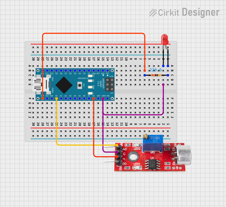
This circuit consists of an Arduino Nano microcontroller, a two-pin red LED, a sound sensor, and a resistor. The Arduino Nano serves as the central processing unit, controlling the LED based on the input from the sound sensor. The sound sensor detects noise levels and provides analog output to the Arduino. The LED acts as an indicator, and the resistor is used to limit the current to the LED to prevent damage.
Component List
Arduino Nano
- Description: A compact microcontroller board based on the ATmega328P.
- Pins: D1/TX, D0/RX, RESET, GND, D2, D3, D4, D5, D6, D7, D8, D9, D10, D11/MOSI, D12/MISO, VIN, 5V, A7, A6, A5, A4, A3, A2, A1, A0, AREF, 3V3, D13/SCK.
LED: Two Pin (red)
- Description: A basic red light-emitting diode.
- Pins: cathode, anode.
Sound Sensor
- Description: A sensor that detects sound and provides both analog and digital outputs.
- Pins: Analog, GND, VCC, Digital.
Resistor
- Description: A passive two-terminal electrical component that implements electrical resistance as a circuit element.
- Pins: pin1, pin2.
- Properties: Resistance: 220 Ohms.
Wiring Details
Arduino Nano
- GND connected to:
- LED (cathode)
- Sound Sensor (GND)
- D13/SCK connected to Resistor (pin1).
- 5V connected to Sound Sensor (VCC).
- A0 connected to Sound Sensor (Analog).
LED: Two Pin (red)
- cathode connected to Arduino Nano (GND).
- anode connected to Resistor (pin2).
Sound Sensor
- Analog connected to Arduino Nano (A0).
- GND connected to Arduino Nano (GND).
- VCC connected to Arduino Nano (5V).
Resistor
- pin1 connected to Arduino Nano (D13/SCK).
- pin2 connected to LED (anode).
Documented Code
No code has been provided for the microcontroller. Typically, this section would include the embedded code written for the Arduino Nano, detailing the functionality and logic used to control the LED based on the sound sensor's input. Since no code is available, this section remains empty. If code becomes available, it should be documented here with comments explaining the purpose and functionality of each section of the code.