
Arduino UNO Based GSM and GPS Tracking System with Motor Control
View and Edit Project In Cirkit Designer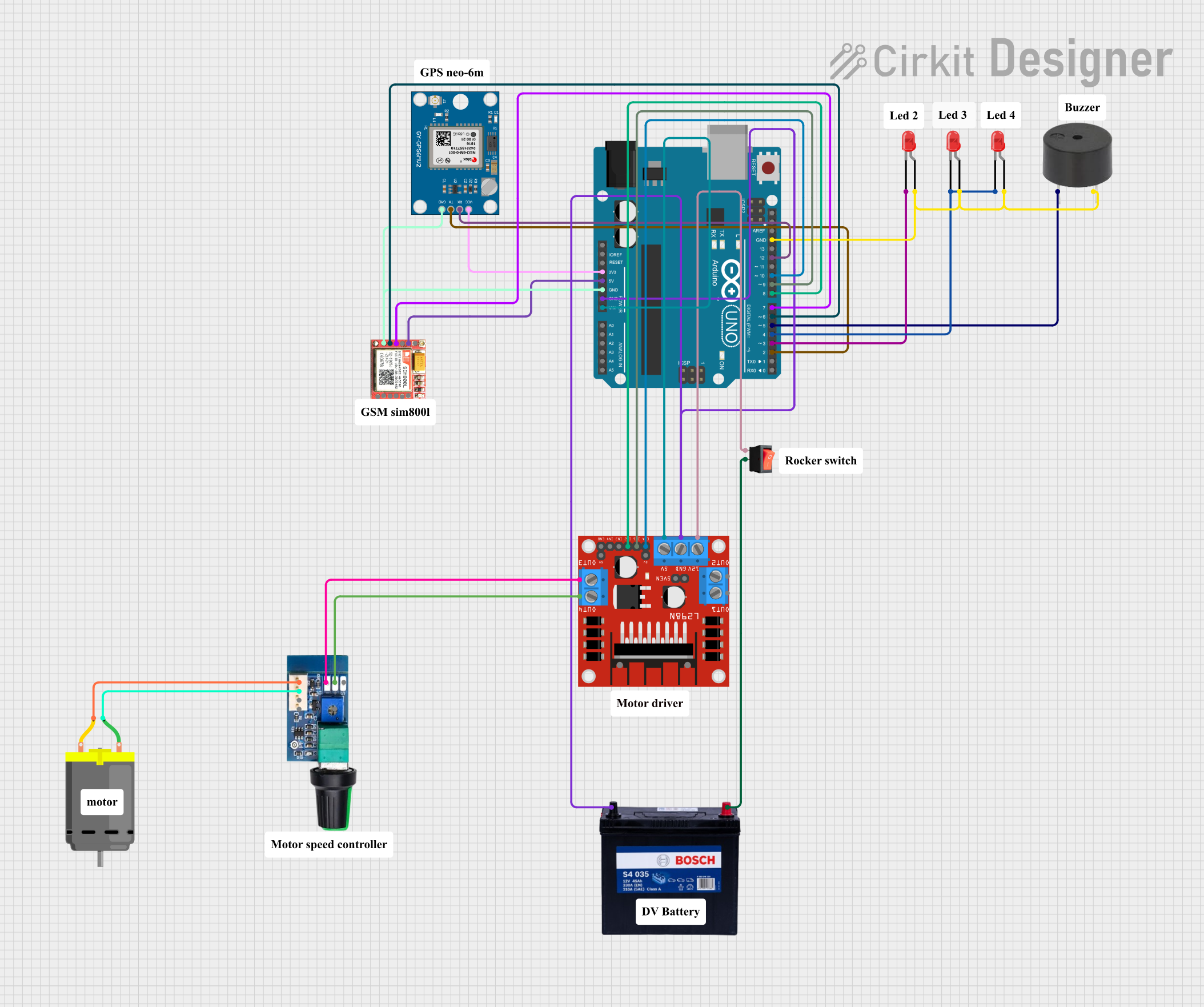
Circuit Documentation
Summary
The circuit is designed to interface an Arduino UNO with a variety of components including a Neo 6M GPS Module, a SIM800L GSM module, a DC motor with a speed controller, and multiple LEDs and a buzzer for signaling purposes. The Arduino UNO is the central processing unit, controlling the motor's operation, receiving GPS data, and communicating via GSM. The circuit is powered by a 12V 200Ah battery, and a rocker switch is used to control the power supply to the motor driver. The DC motor's speed is regulated by a PWM speed controller, and the L298N motor driver interfaces the motor with the Arduino.
Component List
- Arduino UNO: A microcontroller board based on the ATmega328P, with digital and analog I/O pins.
- 12V 200Ah Battery: Provides the power source for the circuit.
- DC 12V PWM Speed Controller: Controls the speed of the DC motor using PWM signals.
- SIM800L: A GSM/GPRS module for cellular communication.
- Neo 6M GPS Module: A GPS receiver module for obtaining geographic location data.
- LED (Red): Three red LEDs used for signaling.
- Buzzer: An audible signaling device.
- DC Motor: An electric motor powered by the DC supply.
- Rocker Switch: A switch to control the power flow to the motor driver.
- L298N DC Motor Driver: A dual H-bridge motor driver for controlling the direction and speed of the motor.
Wiring Details
Arduino UNO
- 3.3V to Neo 6M GPS Module VCC
- 5V to SIM800L VCC
- GND to Neo 6M GPS Module GND, SIM800L GND, Buzzer GND, and all LED anodes
- Vin to L298N Motor Driver 5V
- D12 to Neo 6M GPS Module RX
- D10 to L298N Motor Driver ENA
- D9 to L298N Motor Driver IN1
- D8 to L298N Motor Driver IN2
- D7 to SIM800L RXD
- D6 to SIM800L TXD
- D5 to Buzzer PIN
- D4 to LED cathodes (shared by two LEDs)
- D3 to LED cathode
- D2 to Neo 6M GPS Module TX
12V 200Ah Battery
- GND to Arduino UNO GND, L298N Motor Driver GND
- 12V to Rocker Switch input
DC 12V PWM Speed Controller
- + to L298N Motor Driver OUT4
- - to L298N Motor Driver OUT3
- - Output to DC Motor pin 2
- + Output to DC Motor pin 1
Neo 6M GPS Module
- GND to Arduino UNO GND
- TX to Arduino UNO D2
- RX to Arduino UNO D12
- VCC to Arduino UNO 3.3V
SIM800L
- GND to Arduino UNO GND
- VCC to Arduino UNO 5V
- RXD to Arduino UNO D7
- TXD to Arduino UNO D6
LEDs (Red)
- Anode to Arduino UNO GND
- Cathode to Arduino UNO D3 (one LED), D4 (two LEDs)
Buzzer
- PIN to Arduino UNO D5
- GND to Arduino UNO GND
DC Motor
- Pin 1 to DC 12V PWM Speed Controller + Output
- Pin 2 to DC 12V PWM Speed Controller - Output
Rocker Switch
- Input to L298N Motor Driver 12V
- Output to 12V 200Ah Battery 12V
L298N DC Motor Driver
- GND to Arduino UNO GND
- 5V to Arduino UNO Vin
- 12V to Rocker Switch output
- ENA to Arduino UNO D10
- IN1 to Arduino UNO D9
- IN2 to Arduino UNO D8
- OUT3 to DC 12V PWM Speed Controller -
- OUT4 to DC 12V PWM Speed Controller +
Documented Code
#include <SoftwareSerial.h>
#include <TinyGPS++.h>

SoftwareSerial gsmSerial(6, 7);  // TX for GSM, RX for GSM
SoftwareSerial neo(2, 12);       // TX for GPS, RX for GPS
TinyGPSPlus gps;

// Motor and LED pins
int led1 = 11;
int led2 = 3;
int led3 = 4;
int led4 = 5;
int motorEN = 10;
int motorIN1 = 9;
int motorIN2 = 8;

String textMessage = "";
String lati = "";
String longi = "";

// Variables for non-blocking blinking
unsigned long lastBlinkTime = 0;
bool isBlinking = false;

void setup() {
  Serial.begin(9600);
  gsmSerial.begin(9600);
  delay(5000);
  Serial.println("Initializing GSM...");
  gsmSerial.println("AT");
  checkGSMResponse();
  gsmSerial.println("AT+CMGF=1");
  checkGSMResponse();
  gsmSerial.println("AT+CNMI=2,2,0,0,0");
  checkGSMResponse();

  neo.begin(9600);

  pinMode(led1, OUTPUT);
  pinMode(led2, OUTPUT);
  pinMode(led3, OUTPUT);
  pinMode(led4, OUTPUT);
  pinMode(motorEN, OUTPUT);
  pinMode(motorIN1, OUTPUT);
  pinMode(motorIN2, OUTPUT);

  analogWrite(motorEN, 0);
  digitalWrite(motorIN1, LOW);
  digitalWrite(motorIN2, LOW);
  Serial.println("System initialized.");
}

void loop() {
  gsmSerial.listen();
  delay(2);

  if (gsmSerial.available() > 0) {
    textMessage = gsmSerial.readString();
    textMessage.trim();
    Serial.println("Received message: " + textMessage);

    if (textMessage.indexOf("ON") != -1) {
      handleOnMessage();
    } else if (textMessage.indexOf("OFF") != -1) {
      handleOffMessage();
    } else if (textMessage.indexOf("GETLOC") != -1) {
      handleGetLocMessage();
    }
    textMessage = "";
  }

  blinkLeds34Continuously();
}

void handleOnMessage() {
  Serial.println("Executing ON command");
  digitalWrite(led1, HIGH);
  digitalWrite(motorIN1, HIGH);
  digitalWrite(motorIN2, LOW);
  analogWrite(motorEN, 255);
  stopBlinkingLeds34();
}

void handleOffMessage() {
  Serial.println("Executing OFF command");
  digitalWrite(led1, LOW);
  blinkLED2();
  reduceMotorSpeed();
  startBlinkingLeds34();
}

void blinkLED2() {
  for (int i = 0; i < 5; i++) {
    digitalWrite(led2, HIGH);
    delay(300);
    digitalWrite(led2, LOW);
    delay(300);
  }
}

void reduceMotorSpeed() {
  int reductionDelay = 100;
  int steps = 255 / (10000 / reductionDelay);
  for (int speed = 255; speed >= 0; speed -= steps) {
    analogWrite(motorEN, speed);
    delay(reductionDelay);
  }
  analogWrite(motorEN, 0);
}

void blinkLeds34Continuously() {
  if (!isBlinking) return;

  unsigned long currentMillis = millis();
  if (currentMillis - lastBlinkTime >= 100) {
    lastBlinkTime = currentMillis;
    digitalWrite(led3, !digitalRead(led3));
    digitalWrite(led4, !digitalRead(led4));
  }
}

void startBlinkingLeds34() {
  isBlinking = true;
  lastBlinkTime = millis();
}

void stopBlinkingLeds34() {
  isBlinking = false;
  digitalWrite(led3, LOW);
  digitalWrite(led4, LOW);
}

void handleGetLocMessage() {
  Serial.println("Executing GETLOC command");
  neo.listen();
  smartDelay(1000);
  sendLocationSMS();
}

void sendLocationSMS() {
  gsmSerial.println("AT+CMGS=\"+250728418241\"");
  delay(500);
  String pesan = "https://maps.google.com/?q=" + lati + "," + longi;
  gsmSerial.print(pesan);
  gsmSerial.write(0x1a);
  delay(1000);
  gsmSerial.println("AT+CMGD=1,4");
  Serial.println("Location sent: " + pesan);
}

static void smartDelay(unsigned long ms)