Arduino Mega 2560 Controlled Robotic System with Bluetooth and Sensor Integration
Circuit Documentation
Summary
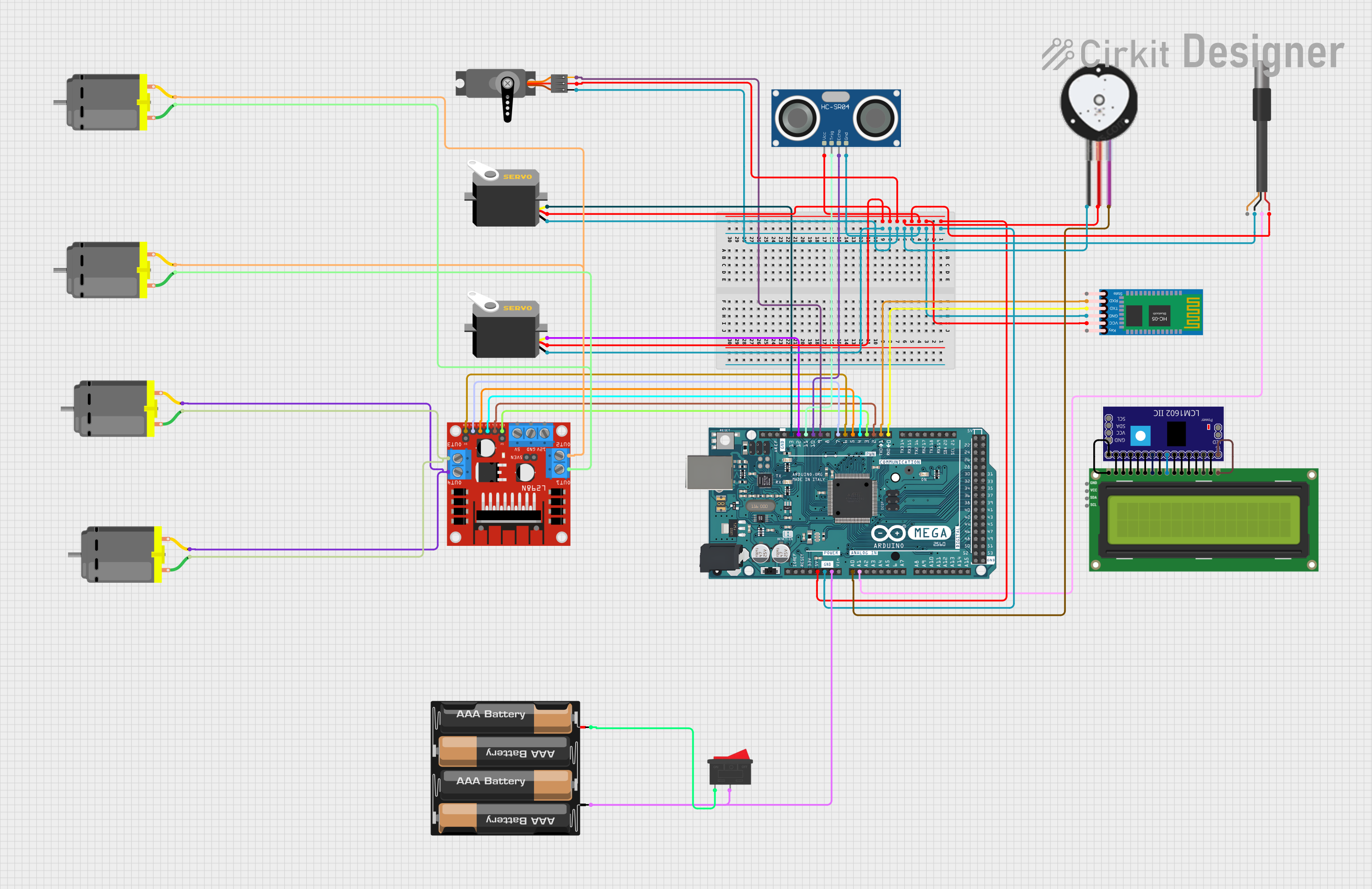
This circuit is designed to interface various sensors, actuators, and modules with an Arduino Mega 2560 microcontroller. The circuit includes a DC motor driver for controlling motors, a heart pulse sensor and a DS18B20 temperature sensor for monitoring health parameters, servos for precise movement control, an HC-05 Bluetooth module for wireless communication, an HC-SR04 ultrasonic sensor for distance measurement, and an I2C LCD screen for data display. Power is supplied by a 4 x AAA battery mount and controlled by a rocker switch.
Component List
L298N DC Motor Driver
- Description: A module used to drive DC motors with direction and speed control.
- Pins: OUT1, OUT2, 12V, GND, 5V, OUT3, OUT4, ENA, IN1, IN2, IN3, IN4, ENB.
Heart Pulse Sensor
- Description: A sensor that measures the heart rate.
- Pins: GND, VCC, SIGNAL.
DS18B20 1-Wire Temperature Sensor Probe Cable
- Description: A digital temperature sensor that uses a one-wire interface.
- Pins: Shield, GND, DQ, VDD.
Servo
- Description: An actuator capable of precise position control.
- Pins: GND, VCC, Pulse/PWM.
HC-05 Bluetooth Module
- Description: A wireless communication module for Bluetooth connectivity.
- Pins: Key, VCC, TXD, RXD, State, GND.
HC-SR04 Ultrasonic Sensor
- Description: A sensor for measuring distance using ultrasonic waves.
- Pins: VCC, TRIG, ECHO, GND.
I2C LCD 16x2 Screen
- Description: A liquid crystal display for showing text and numbers.
- Pins: SCL, SDA, VCC (5V), GND, VDD, VO, RS, RW, E, D0-D7, BLA, BLK.
LCM1602 IIC
- Description: An I2C interface module for LCD screens.
- Pins: GND, VCC, SDA, SCL, D0-D7, RS, RW, E, A, K, VSS, VDD, V0.
Arduino Mega 2560
- Description: A microcontroller board based on the ATmega2560.
- Pins: Various digital and analog pins, power, and ground.
DC Motor
- Description: An electric motor that runs on direct current (DC).
- Pins: Pin 1, Pin 2.
4 x AAA Battery Mount
- Description: A battery holder for four AAA batteries.
- Pins: +, -.
Rocker Switch
- Description: A switch to control the power supply.
- Pins: 1, 2.
Wiring Details
L298N DC Motor Driver
- 5V: Connected to Arduino 5V.
- GND: Connected to Arduino GND.
- IN1, IN2, IN3, IN4: Connected to Arduino digital pins D2, D4, D5, D7 respectively.
- ENA, ENB: Connected to Arduino digital pins D3, D6 respectively.
- OUT1, OUT2, OUT3, OUT4: Connected to DC motors.
Heart Pulse Sensor
- VCC: Connected to Arduino 5V.
- GND: Connected to Arduino GND.
- SIGNAL: Connected to Arduino analog pin A0.
DS18B20 1-Wire Temperature Sensor Probe Cable
- VDD: Connected to Arduino 5V.
- GND: Connected to Arduino GND.
- DQ: Connected to Arduino analog pin A1.
Servo
- VCC: Connected to Arduino 5V.
- GND: Connected to Arduino GND.
- Pulse/PWM: Connected to Arduino digital pins D9, D12, D13.
HC-05 Bluetooth Module
- VCC: Connected to Arduino 5V.
- GND: Connected to Arduino GND.
- TXD: Connected to Arduino digital pin D0 (RX0).
- RXD: Connected to Arduino digital pin D1 (TX0).
HC-SR04 Ultrasonic Sensor
- VCC: Connected to Arduino 5V.
- GND: Connected to Arduino GND.
- TRIG: Connected to Arduino digital pin D11.
- ECHO: Connected to Arduino digital pin D10.
I2C LCD 16x2 Screen and LCM1602 IIC
- GND: Connected to each other.
- VDD: Connected to each other.
- VO: Connected to each other.
- RS, RW, E, D0-D7: Connected to each other.
- BLA: Connected to each other.
- BLK: Connected to each other.
DC Motor
- Pin 1 and Pin 2: Connected to L298N DC motor driver OUT pins.
4 x AAA Battery Mount
- +: Connected to Rocker Switch pin 1.
- -: Connected to Arduino GND.
Rocker Switch
- Pin 2: Connected to Arduino GND.
Documented Code
void setup() {
  // put your setup code here, to run once:

}

void loop() {
  // put your main code here, to run repeatedly:

}
The provided code is a template for the Arduino Mega 2560 microcontroller. The setup() function is called once when the microcontroller is powered on or reset. The loop() function is called repeatedly and contains the main logic of the program. Specific code to control the sensors, actuators, and communication modules needs to be added to these functions.