
Arduino UNO-Based Smart Light System with RGB LED and Photocell Sensors
View and Edit Project In Cirkit Designer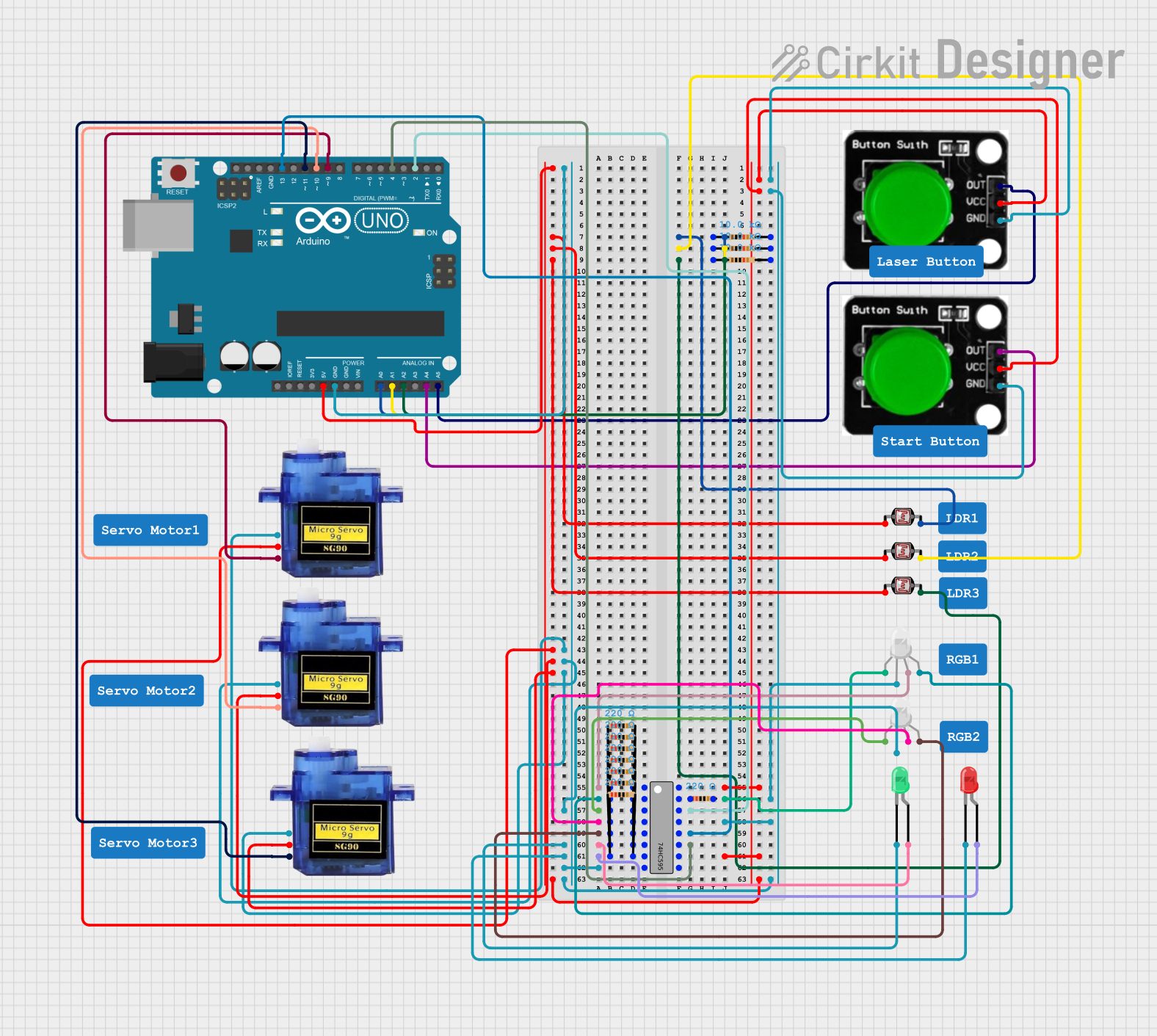
Circuit Documentation
Summary
This circuit involves an Arduino UNO microcontroller interfacing with various components including green buttons, photocells (LDRs), micro servos, RGB LEDs, and a 74HC595 shift register. The circuit is designed to read inputs from the buttons and photocells, control the servos, and manage the RGB LEDs through the shift register.
Component List
Arduino UNO
- Description: A microcontroller board based on the ATmega328P.
- Pins: UNUSED, IOREF, Reset, 3.3V, 5V, GND, Vin, A0, A1, A2, A3, A4, A5, SCL, SDA, AREF, D13, D12, D11, D10, D9, D8, D7, D6, D5, D4, D3, D2, D1, D0
Green Button
- Description: A simple push button.
- Pins: OUT, VCC, GND
Photocell (LDR)
- Description: A light-dependent resistor.
- Pins: pin 0, pin 1
Micro Servo 9G
- Description: A small servo motor.
- Pins: GND, +5V, PWM
RGB LED (Wokwi compatible)
- Description: An RGB LED with common anode.
- Pins: R, COM, G, B
LED: Two Pin (green)
- Description: A standard green LED.
- Pins: cathode, anode
LED: Two Pin (red)
- Description: A standard red LED.
- Pins: cathode, anode
Resistor
- Description: A resistor with various resistance values.
- Pins: pin1, pin2
- Properties:
- Resistance: 10k Ohms, 220 Ohms
74HC595
- Description: An 8-bit shift register.
- Pins: Q1, Q2, Q3, Q4, Q5, Q6, Q7, GND, VCC, Q0, DS (DATA), OE (Enable), ST_CP (RCLK), SH_CP (SRCLK), MR (SRCLR), Q7' (QH)
Wiring Details
Arduino UNO
- A0: Connected to pin1 of a 10k Ohm resistor and pin 1 of a photocell (LDR).
- A1: Connected to pin1 of a 10k Ohm resistor and pin 1 of a photocell (LDR).
- A2: Connected to pin1 of a 10k Ohm resistor and pin 1 of a photocell (LDR).
- A4: Connected to OUT pin of a green button.
- A5: Connected to OUT pin of a green button.
- D2: Connected to DS (DATA) pin of the 74HC595.
- D4: Connected to SH_CP (SRCLK) pin of the 74HC595.
- D9: Connected to PWM pin of a micro servo.
- D10: Connected to PWM pin of a micro servo.
- D11: Connected to PWM pin of a micro servo.
- D13: Connected to ST_CP (RCLK) pin of the 74HC595.
- 5V: Connected to VCC pins of the 74HC595, green buttons, and pin 0 of photocells.
- GND: Connected to GND pins of the 74HC595, green buttons, RGB LEDs, and micro servos.
Green Button
- OUT: Connected to A4 or A5 of the Arduino UNO.
- VCC: Connected to 5V of the Arduino UNO.
- GND: Connected to GND of the Arduino UNO.
Photocell (LDR)
- pin 0: Connected to 5V of the Arduino UNO.
- pin 1: Connected to pin1 of a 10k Ohm resistor and A0, A1, or A2 of the Arduino UNO.
Micro Servo 9G
- GND: Connected to GND of the Arduino UNO.
- +5V: Connected to 5V of the Arduino UNO.
- PWM: Connected to D9, D10, or D11 of the Arduino UNO.
RGB LED (Wokwi compatible)
- R: Connected to pin2 of a 220 Ohm resistor and Q0 or Q3 of the 74HC595.
- COM: Connected to GND of the Arduino UNO.
- G: Connected to pin2 of a 220 Ohm resistor and Q1 or Q4 of the 74HC595.
- B: Connected to pin2 of a 220 Ohm resistor and Q2 or Q5 of the 74HC595.
LED: Two Pin (green)
- cathode: Connected to GND of the Arduino UNO.
- anode: Connected to pin2 of a 220 Ohm resistor and Q6 of the 74HC595.
LED: Two Pin (red)
- cathode: Connected to GND of the Arduino UNO.
- anode: Connected to pin2 of a 220 Ohm resistor and Q7 of the 74HC595.
Resistor
- 10k Ohm Resistors:
- pin1: Connected to A0, A1, or A2 of the Arduino UNO.
- pin2: Connected to pin 1 of a photocell (LDR).
- 220 Ohm Resistors:
- pin1: Connected to Q0, Q1, Q2, Q3, Q4, Q5, Q6, or Q7 of the 74HC595.
- pin2: Connected to R, G, B pins of RGB LEDs or anode of two-pin LEDs.
74HC595
- Q0: Connected to pin1 of a 220 Ohm resistor and R pin of an RGB LED.
- Q1: Connected to pin1 of a 220 Ohm resistor and G pin of an RGB LED.
- Q2: Connected to pin1 of a 220 Ohm resistor and B pin of an RGB LED.
- Q3: Connected to pin1 of a 220 Ohm resistor and R pin of an RGB LED.
- Q4: Connected to pin1 of a 220 Ohm resistor and G pin of an RGB LED.
- Q5: Connected to pin1 of a 220 Ohm resistor and B pin of an RGB LED.
- Q6: Connected to pin1 of a 220 Ohm resistor and anode of a green LED.
- Q7: Connected to pin1 of a 220 Ohm resistor and anode of a red LED.
- VCC: Connected to 5V of the Arduino UNO.
- GND: Connected to GND of the Arduino UNO.
- DS (DATA): Connected to D2 of the Arduino UNO.
- OE (Enable): Connected to GND of the Arduino UNO.
- ST_CP (RCLK): Connected to D13 of the Arduino UNO.
- SH_CP (SRCLK): Connected to D4 of the Arduino UNO.
- MR (SRCLR): Connected to 5V of the Arduino UNO.
Documented Code
Arduino UNO Code
void setup() {
  // put your setup code here, to run once:

}

void loop() {
  // put your main code here, to run repeatedly:

}
This code is a basic template for the Arduino UNO. The setup() function is used to initialize any settings or configurations, and the loop() function contains the main code that runs repeatedly.