Arduino Nano Solar-Powered Environmental Monitoring System with RF Transmission
Circuit Documentation
Summary
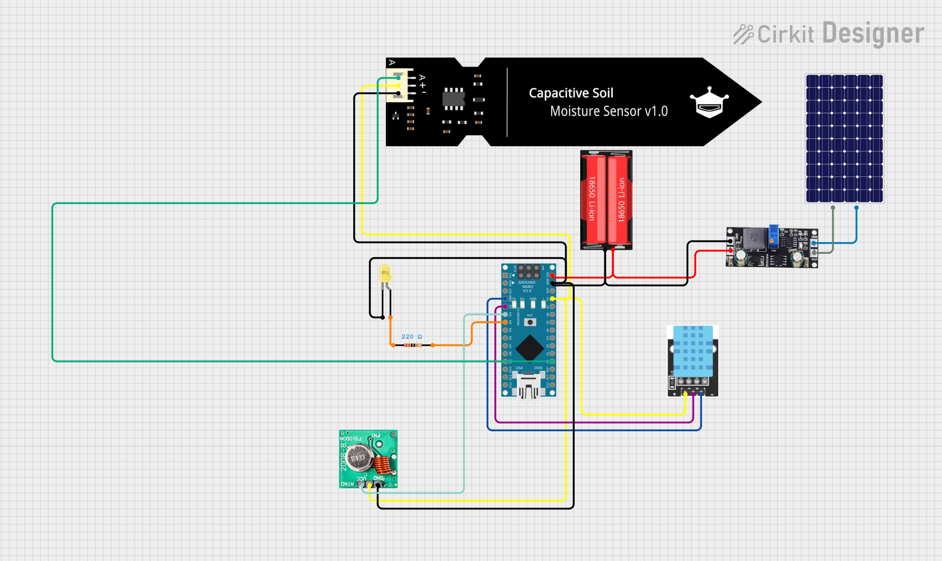
This document provides a detailed overview of a circuit designed to monitor environmental conditions and transmit data wirelessly. The circuit includes an Arduino Nano microcontroller, a temperature-humidity sensor, a soil moisture sensor, an RF transmitter, a solar panel, a battery, and an LED indicator. The system is powered by a solar panel and a rechargeable 18650 Li-Ion battery, managed by an MPPT charge controller.
Component List
18650 Li-Ion Battery
- Description: Rechargeable lithium-ion battery.
- Pins: Positive, Negative
Arduino Nano
- Description: Microcontroller board based on the ATmega328P.
- Pins: D1/TX, D0/RX, RESET, GND, D2, D3, D4, D5, D6, D7, D8, D9, D10, D11/MOSI, D12/MISO, VIN, 5V, A7, A6, A5, A4, A3, A2, A1, A0, AREF, 3V3, D13/SCK
KY-015 DHT11 Temperature-Humidity Sensor Module
- Description: Sensor module for measuring temperature and humidity.
- Pins: VCC, GND, DOUT
FS1000A 433MHz RF Transmitter
- Description: Wireless RF transmitter module.
- Pins: DATA, VCC, GND, ANT
DFRobot Capacitive Soil Moisture Sensor (V1.0)
- Description: Sensor for measuring soil moisture levels.
- Pins: A, VCC, GND
Solar Panel
- Description: Solar panel for generating electrical power.
- Pins: +, -
SD30CRMA MPPT
- Description: Maximum Power Point Tracking (MPPT) charge controller.
- Pins: GND, VIN, BAT
LED: Two Pin (Yellow)
- Description: Yellow LED indicator.
- Pins: Cathode, Anode
Resistor
- Description: 220 Ohms resistor.
- Pins: Pin1, Pin2
Wiring Details
18650 Li-Ion Battery
- Positive: Connected to BAT pin of SD30CRMA MPPT and VIN pin of Arduino Nano.
- Negative: Connected to GND pins of SD30CRMA MPPT, FS1000A RF Transmitter, DFRobot Soil Moisture Sensor, Arduino Nano, LED (cathode), and KY-015 DHT11 Sensor.
Arduino Nano
- VIN: Connected to BAT pin of SD30CRMA MPPT and Positive pin of 18650 Li-Ion Battery.
- GND: Connected to GND pins of SD30CRMA MPPT, FS1000A RF Transmitter, DFRobot Soil Moisture Sensor, LED (cathode), and KY-015 DHT11 Sensor.
- D2: Connected to DOUT pin of KY-015 DHT11 Sensor.
- D3: Connected to DATA pin of FS1000A RF Transmitter.
- D4: Connected to Pin2 of Resistor.
- 5V: Connected to VCC pins of KY-015 DHT11 Sensor, FS1000A RF Transmitter, and DFRobot Soil Moisture Sensor.
- A0: Connected to A pin of DFRobot Soil Moisture Sensor.
KY-015 DHT11 Temperature-Humidity Sensor Module
- VCC: Connected to 5V pin of Arduino Nano.
- GND: Connected to GND pin of Arduino Nano.
- DOUT: Connected to D2 pin of Arduino Nano.
FS1000A 433MHz RF Transmitter
- DATA: Connected to D3 pin of Arduino Nano.
- VCC: Connected to 5V pin of Arduino Nano.
- GND: Connected to GND pin of Arduino Nano.
DFRobot Capacitive Soil Moisture Sensor (V1.0)
- A: Connected to A0 pin of Arduino Nano.
- VCC: Connected to 5V pin of Arduino Nano.
- GND: Connected to GND pin of Arduino Nano.
Solar Panel
- +: Connected to VIN pin of SD30CRMA MPPT.
- -: Connected to GND pin of SD30CRMA MPPT.
SD30CRMA MPPT
- BAT: Connected to Positive pin of 18650 Li-Ion Battery and VIN pin of Arduino Nano.
- VIN: Connected to + pin of Solar Panel.
- GND: Connected to - pin of Solar Panel and GND pins of FS1000A RF Transmitter, DFRobot Soil Moisture Sensor, Arduino Nano, LED (cathode), and KY-015 DHT11 Sensor.
LED: Two Pin (Yellow)
- Anode: Connected to Pin1 of Resistor.
- Cathode: Connected to GND pin of Arduino Nano.
Resistor
- Pin1: Connected to Anode pin of LED.
- Pin2: Connected to D4 pin of Arduino Nano.
Documented Code
Arduino Nano Code
void setup() {
  // put your setup code here, to run once:

}

void loop() {
  // put your main code here, to run repeatedly:

}
This code is a basic template for the Arduino Nano. The setup() function is used to initialize any settings or configurations, and the loop() function contains the main logic that runs repeatedly. Further code can be added to read sensor data, control the RF transmitter, and manage other functionalities as required by the application.