Cirkit Designer
Your all-in-one circuit design IDE
Home /
Project Documentation
Arduino UNO-Based Alcohol Detection System with Buzzer and LED Alert
Circuit Documentation
Summary
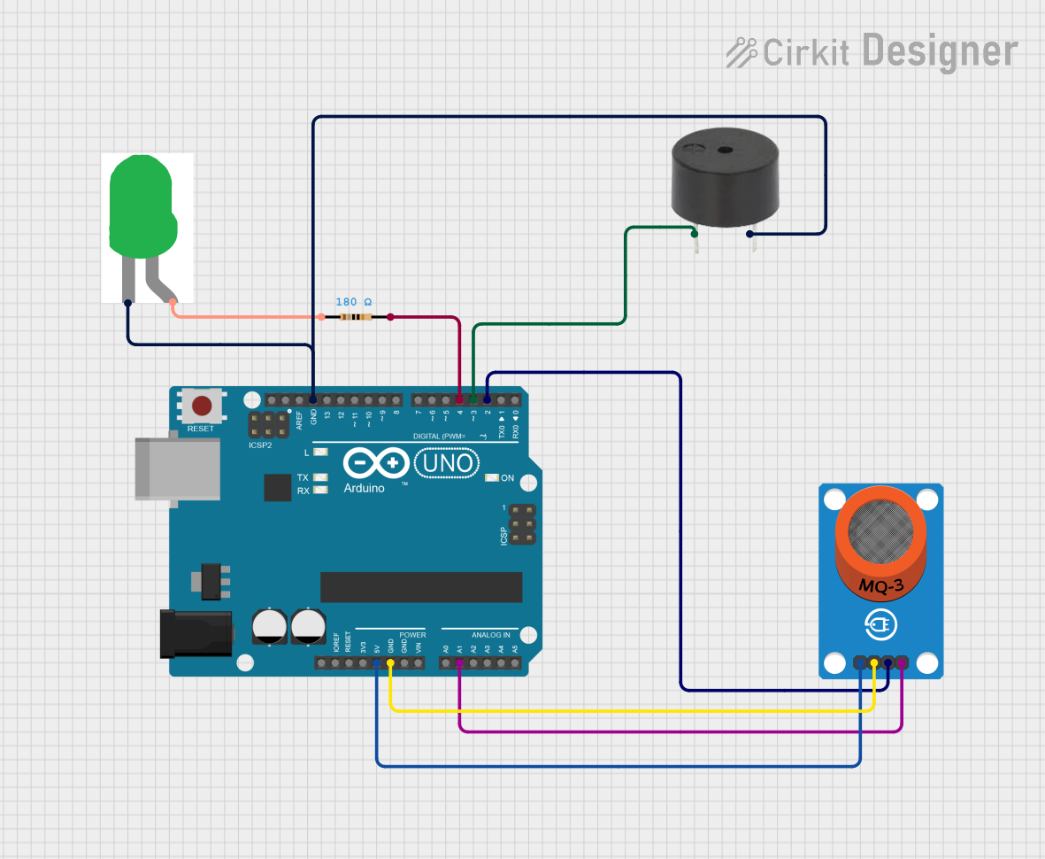
This circuit is designed to interface an MQ-3 gas sensor with an Arduino UNO. The circuit includes a buzzer and an LED to provide visual and auditory alerts based on the sensor readings. The Arduino UNO reads both digital and analog signals from the MQ-3 sensor and controls the LED and buzzer accordingly.
Component List
Arduino UNO
- Description: A microcontroller board based on the ATmega328P.
- Pins: UNUSED, IOREF, Reset, 3.3V, 5V, GND, Vin, A0, A1, A2, A3, A4, A5, SCL, SDA, AREF, D13, D12, D11, D10, D9, D8, D7, D6, D5, D4, D3, D2, D1, D0
Buzzer
- Description: An electronic device that produces a sound when a voltage is applied.
- Pins: PIN, GND
Resistor
- Description: A passive electrical component with a resistance of 180 Ohms.
- Pins: pin1, pin2
MQ-3 Breakout
- Description: A gas sensor module that detects alcohol.
- Pins: VCC, GND, DO, AO
LED: Two Pin (green)
- Description: A green light-emitting diode.
- Pins: cathode, anode
Wiring Details
Arduino UNO
- 5V connected to VCC of MQ-3 Breakout
- GND connected to GND of MQ-3 Breakout
- GND connected to GND of Buzzer
- GND connected to cathode of LED: Two Pin (green)
- A1 connected to AO of MQ-3 Breakout
- D4 connected to pin2 of Resistor
- D3 connected to PIN of Buzzer
- D2 connected to DO of MQ-3 Breakout
Buzzer
- GND connected to GND of Arduino UNO
- PIN connected to D3 of Arduino UNO
Resistor
- pin1 connected to anode of LED: Two Pin (green)
- pin2 connected to D4 of Arduino UNO
MQ-3 Breakout
- VCC connected to 5V of Arduino UNO
- GND connected to GND of Arduino UNO
- DO connected to D2 of Arduino UNO
- AO connected to A1 of Arduino UNO
LED: Two Pin (green)
- cathode connected to GND of Arduino UNO
- anode connected to pin1 of Resistor
Code Documentation
/* MQ-3 sensor with Arduino.
   created by the SriTu Tech team.
   Read the code below and use it for any of your creations.
   Home Page
*/

#define sensorDigital 2
#define LED 3
#define buzzer 4
#define sensorAnalog A1

void setup() {
  pinMode(sensorDigital, INPUT);
  pinMode(LED, OUTPUT);
  pinMode(buzzer, OUTPUT);
  Serial.begin(9600);
}

void loop() {
  bool digital = digitalRead(sensorDigital);
  int analog = analogRead(sensorAnalog);

  Serial.print("Analog value : ");
  Serial.print(analog);
  Serial.print("\t");
  Serial.print("Digital value :");
  Serial.println(digital);

  if (digital == 0) {
    digitalWrite(LED, HIGH);
    digitalWrite(buzzer, HIGH);
  } else {
    digitalWrite(LED, LOW);
    digitalWrite(buzzer, LOW);
  }
}
Code Explanation
- sensorDigital: Digital pin connected to the digital output (DO) of the MQ-3 sensor.
- LED: Digital pin connected to the buzzer.
- buzzer: Digital pin connected to the LED.
- sensorAnalog: Analog pin connected to the analog output (AO) of the MQ-3 sensor.
In the setup function, the pins are initialized, and the serial communication is started. The loop function reads the digital and analog values from the MQ-3 sensor and prints them to the serial monitor. If the digital value is low, the LED and buzzer are turned on; otherwise, they are turned off.