Arduino UNO Controlled LCD Display with Pushbutton Interaction
Circuit Documentation
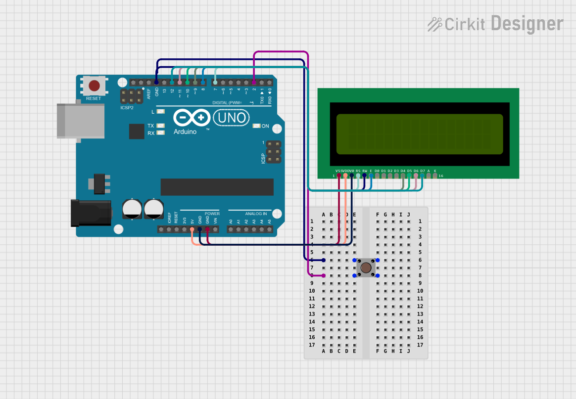
Summary of the Circuit
This circuit integrates an Arduino UNO microcontroller with a 16x2 LCD display and a pushbutton. The Arduino UNO is used as the central processing unit, controlling the display output on the LCD and reading the input from the pushbutton. The LCD is used to display text messages and the pushbutton serves as a user input device. The circuit is powered by the Arduino UNO's 5V output, which is connected to the LCD, and the ground connections are shared among the components.
Component List
Arduino UNO
- Description: A microcontroller board based on the ATmega328P.
- Purpose: Acts as the central processing unit for the circuit, controlling the LCD and reading the pushbutton state.
- Pins: UNUSED, IOREF, Reset, 3.3V, 5V, GND, Vin, A0-A5, SCL, SDA, AREF, D0-D13.
Pushbutton
- Description: A simple switch mechanism for controlling some aspect of a machine or a process.
- Purpose: Provides a user interface to trigger an event when pressed.
- Pins: Pin 3 (out), Pin 4 (out), Pin 1 (in), Pin 2 (in).
16X2 LCD
- Description: A liquid crystal display capable of displaying 16 characters per line across 2 lines.
- Purpose: Displays information to the user.
- Pins: VSS, VDD, V0, RS, RW, E, D0-D7, A, K.
Wiring Details
Arduino UNO
- 5V connected to 16X2 LCD VDD
- GND connected to 16X2 LCD V0, VSS, and Pushbutton Pin 3 (out)
- D2 connected to Pushbutton Pin 1 (in)
- D7 connected to 16X2 LCD RS
- D8 connected to 16X2 LCD E
- D9 connected to 16X2 LCD D4
- D10 connected to 16X2 LCD D5
- D11 connected to 16X2 LCD D6
- D12 connected to 16X2 LCD D7
Pushbutton
- Pin 1 (in) connected to Arduino UNO D2
- Pin 3 (out) connected to Arduino UNO GND
16X2 LCD
- VDD connected to Arduino UNO 5V
- V0 connected to Arduino UNO GND
- VSS connected to Arduino UNO GND
- RS connected to Arduino UNO D7
- RW connected to Pushbutton Pin 3 (out) and Arduino UNO GND
- E connected to Arduino UNO D8
- D4 connected to Arduino UNO D9
- D5 connected to Arduino UNO D10
- D6 connected to Arduino UNO D11
- D7 connected to Arduino UNO D12
Documented Code
/*
RS -> D7
E -> D8
D4 -> D9
D5 -> D10
D6 -> D11
D7 -> D12
*/

// Include the LiquidCrystal library
#include <LiquidCrystal.h>

// Initialize the library with the numbers of the interface pins
LiquidCrystal lcd(7, 8, 9, 10, 11, 12);

void setup() {
  // Set up the LCD's number of columns and rows:
  lcd.begin(16, 2);
  // Print a message to the LCD.
  lcd.print("Hello, World!");
}

void loop() {
  // Set the cursor to column 0, line 1
  // (note: line 1 is the second row, since counting begins with 0):
  lcd.setCursor(0, 1);
  // Print the number of seconds since reset:
  lcd.print(millis() / 1000);
}
This code initializes the 16x2 LCD and prints "Hello, World!" on the first line. On the second line, it continuously updates and displays the number of seconds since the Arduino UNO was last reset. The LCD interface pins are connected to the digital pins D7 to D12 on the Arduino UNO.