ESP32-Controlled Water Level Monitoring System with LCD Display and Alert Indicators
Circuit Documentation
Summary
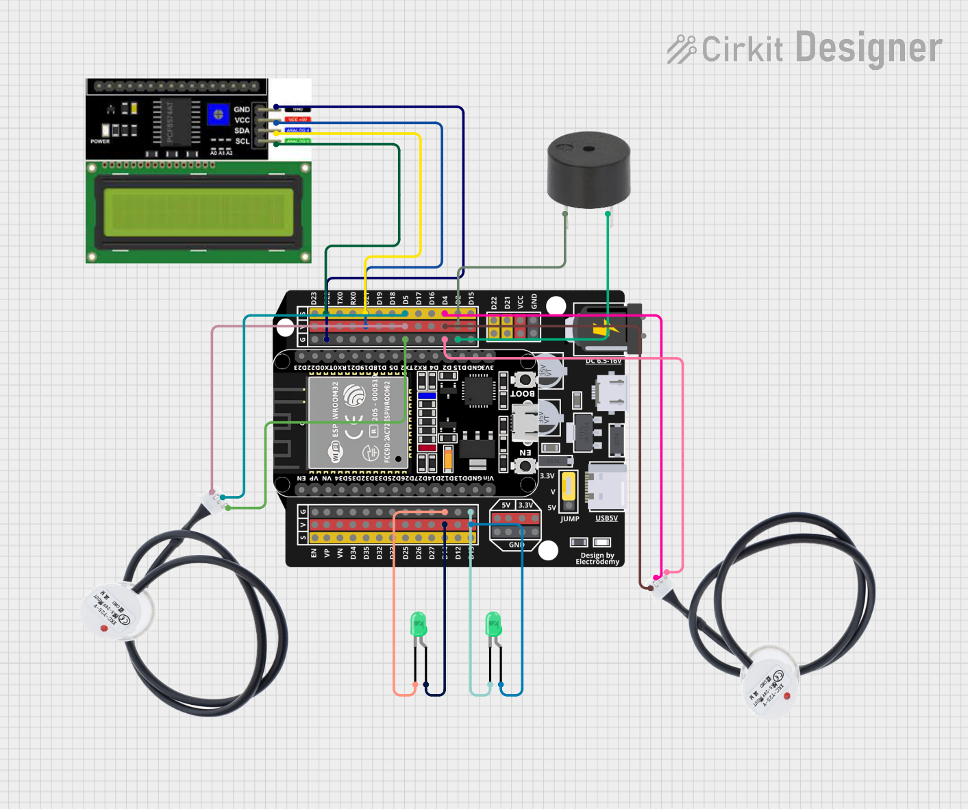
The circuit in question is designed to monitor water levels using non-contact water level sensors and display the status on an LCD I2C display. It also includes visual indicators in the form of LEDs and an audible alert using a buzzer. The core of the circuit is an ESP32 Expansion Board, which controls the sensors, processes the input signals, and manages the output devices.
Component List
Non-contact Water Level Sensor
- Description: A sensor that detects water levels without requiring physical contact with the water.
- Pins: VCC, GND, SIG
LCD I2C Display
- Description: A display module with I2C communication interface for showing information.
- Pins: GND, VCC, SDA, SCL
Buzzer
- Description: An audible signaling device.
- Pins: PIN, GND
LED: Two Pin (Green)
- Description: A green light-emitting diode for visual indication.
- Pins: Cathode, Anode
ESP32 - Expansion Board
- Description: A microcontroller board with Wi-Fi and Bluetooth capabilities, used as the main controller in the circuit.
- Pins: +, -, EN, VP, VN, D34, D32, D33, D25, D26, D27, D14, D12, D13, D23, D22, TX0, RX0, D21, D19, D18, D5, D17, D16, D4, D2, D15, VCC, G, 5V, 3.3V, V
Wiring Details
Non-contact Water Level Sensor
- VCC connected to ESP32 Expansion Board V
- GND connected to ESP32 Expansion Board G
- SIG connected to ESP32 Expansion Board D5 (for the first sensor) and D4 (for the second sensor)
LCD I2C Display
- GND connected to ESP32 Expansion Board G
- VCC connected to ESP32 Expansion Board V
- SDA connected to ESP32 Expansion Board D21
- SCL connected to ESP32 Expansion Board D22
Buzzer
- PIN connected to ESP32 Expansion Board V
- GND connected to ESP32 Expansion Board G
LED: Two Pin (Green)
- Cathode connected to ESP32 Expansion Board G
- Anode connected to ESP32 Expansion Board V
Documented Code
Since no code was provided in the input, this section cannot be completed. However, once the code is available, it should be documented here with comments explaining the functionality of each part of the code, including setup, main loop, and any functions or libraries used.
Please note that the instance IDs have been omitted from this document as per the instructions. If you need to reference specific instances of components, such as when multiple components of the same type are used, you should include the instance IDs in your internal documentation for clarity.