Cirkit Designer
Your all-in-one circuit design IDE
Home /
Project Documentation
Arduino UNO-Based Robotic Arm with Servo Motors and LED Control
Circuit Documentation
Summary
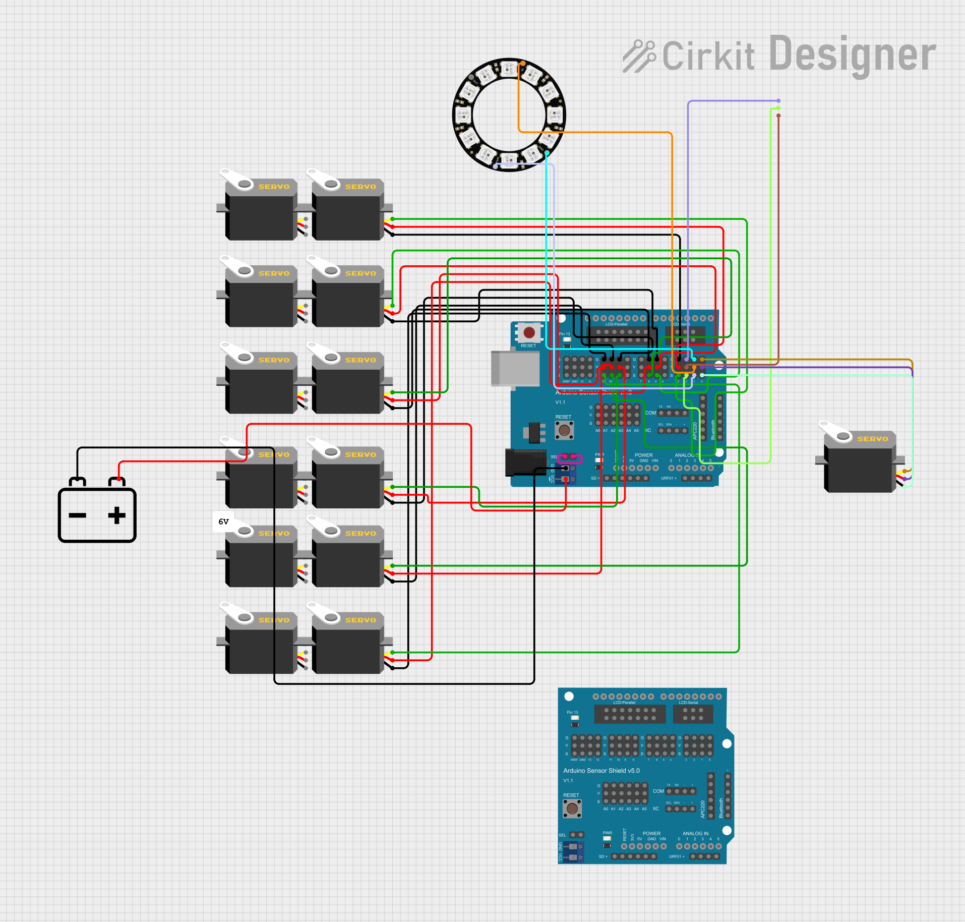
This circuit involves an Arduino UNO microcontroller connected to an Arduino Sensor Shield v5.0, which interfaces with multiple servos, an LED RGB strip, and an Adafruit 12 NeoPixel Ring. The circuit is powered by a 12V battery. The Arduino UNO is programmed to control the servos and read distances using ultrasonic sensors.
Component List
Arduino UNO
- Description: Microcontroller board based on the ATmega328P.
- Pins: UNUSED, IOREF, Reset, 3.3V, 5V, GND, Vin, A0, A1, A2, A3, A4, A5, SCL, SDA, AREF, D13, D12, D11, D10, D9, D8, D7, D6, D5, D4, D3, D2, D1, D0
Arduino Sensor Shield v5.0
- Description: Expansion shield for Arduino UNO to easily connect sensors and servos.
- Pins: VCC, SD-VCC, SD-GND, SD-D11, SD-D10, SD-D13, SD-D12, URF01-VCC, URF01-A0, URF01-A1, URF01-GND, GND, SEL1, SEL2, A0-SIG, A0-VCC, A0-GND, A1-SIG, A1-VCC, A1-GND, A2-SIG, A2-VCC, A2-GND, A3-SIG, A3-VCC, A3-GND, A4-SIG, A4-VCC, A4-GND, A5-SIG, A5-VCC, A5-GND, IIC-SCL, IIC-SDA, IIC-GND, IIC-VCC, COM-TX, COM-RX, COM-GND, COM-VCC, APC220-, APC220-D0, APC220-D1, APC220-VCC, APC220-GND, BLUETOOTH-3V3, BLUETOOTH-GND, BLUETOOTH-D0, BLUETOOTH-D1, BLUETOOTH-VCC, AREF-S, AREF-V, AREF-G, GND-S, GND-V, GND-G, 13-S, 13-V, 13-G, 12-S, 12-V, 12-G, 11-S, 11-V, 11-G, 10-S, 10-V, 10-G, 9-S, 9-V, 9-G, 8-S, 8-V, 8-G, 7-S, 7-V, 7-G, 6-S, 6-V, 6-G, 5-S, 5-V, 5-G, 4-S, 4-V, 4-G, 3-S, 3-V, 3-G, 2-S, 2-V, 2-G, 1-S, 1-V, 1-G, 0-S, 0-V, 0-G, ParallelLCD-VCC, ParallelLCD-D13, ParallelLCD-GND, ParallelLCD-D12, ParallelLCD-D2, ParallelLCD-D11, ParallelLCD-D3, ParallelLCD-D10, ParallelLCD-D4, ParallelLCD-D9, ParallelLCD-D5, ParallelLCD-D8, ParallelLCD-D6, ParallelLCD-D7, SerialLCD-D4, SerialLCD-VCC, SerialLCD-D3, SerialLCD-, SerialLCD-D2, SerialLCD-GND
Servo
- Description: Standard servo motor.
- Pins: gnd, vcc, pulse
12V Battery
- Description: Power source for the circuit.
- Pins: +, -
Adafruit 12 NeoPixel Ring
- Description: Ring of 12 individually addressable RGB LEDs.
- Pins: OUT, VDD, IN, GND
LED RGB Strip
- Description: RGB LED strip with common anode.
- Pins: Common Connect, Blue Connect, Red Connect, Green Connect
Wiring Details
Arduino UNO
- 5V: Connected to Arduino Sensor Shield v5.0 VCC
- GND: Connected to Arduino Sensor Shield v5.0 GND
Arduino Sensor Shield v5.0
- VCC: Connected to 12V Battery +
- GND: Connected to 12V Battery -
- SEL1: Connected to SEL2 on the same shield
- 11-S: Connected to Servo pulse
- 11-V: Connected to Servo vcc
- 11-G: Connected to Servo gnd
- 10-S: Connected to Servo pulse
- 10-V: Connected to Servo vcc
- 10-G: Connected to Servo gnd
- 9-S: Connected to Servo pulse
- 9-V: Connected to Servo vcc
- 9-G: Connected to Servo gnd
- 6-S: Connected to Servo pulse
- 6-V: Connected to Servo vcc
- 6-G: Connected to Servo gnd
- 5-S: Connected to Servo pulse
- 5-V: Connected to Servo vcc
- 5-G: Connected to Servo gnd
- 3-S: Connected to Servo pulse
- 3-V: Connected to Servo vcc
- 3-G: Connected to Servo gnd
- 2-S: Connected to LED RGB Strip Red Connect
- 2-V: Connected to LED RGB Strip Blue Connect
- 2-G: Connected to LED RGB Strip Green Connect
- 1-S: Connected to Adafruit 12 NeoPixel Ring VDD
- 1-V: Connected to Adafruit 12 NeoPixel Ring IN
- 1-G: Connected to Adafruit 12 NeoPixel Ring GND
- 0-S: Connected to Servo gnd
- 0-V: Connected to Servo vcc
- 0-G: Connected to Servo pulse
Servo
- gnd: Connected to Arduino Sensor Shield v5.0 11-G, 10-G, 9-G, 6-G, 5-G, 3-G, 0-S
- vcc: Connected to Arduino Sensor Shield v5.0 11-V, 10-V, 9-V, 6-V, 5-V, 3-V, 0-V
- pulse: Connected to Arduino Sensor Shield v5.0 11-S, 10-S, 9-S, 6-S, 5-S, 3-S, 0-G
12V Battery
- +: Connected to Arduino Sensor Shield v5.0 VCC
- -: Connected to Arduino Sensor Shield v5.0 GND
Adafruit 12 NeoPixel Ring
- VDD: Connected to Arduino Sensor Shield v5.0 1-S
- IN: Connected to Arduino Sensor Shield v5.0 1-V
- GND: Connected to Arduino Sensor Shield v5.0 1-G
LED RGB Strip
- Red Connect: Connected to Arduino Sensor Shield v5.0 2-S
- Blue Connect: Connected to Arduino Sensor Shield v5.0 2-V
- Green Connect: Connected to Arduino Sensor Shield v5.0 2-G
Code Documentation
#include <Servo.h>

volatile int IN1 = 11;
volatile int IN2 = 6;
volatile int IN3 = 5;
volatile int IN4 = 3;
volatile int rightDistance;
volatile int leftDistance;
Servo servo_4;

void left_side_forward(int speed) {
  analogWrite(IN1, speed * 0.92);
  analogWrite(IN2, 0);
}

void right_side_forward(int speed) {
  analogWrite(IN3, speed);
  analogWrite(IN4, 0);
}

void left_side_backward(int speed) {
  analogWrite(IN1, 0);
  analogWrite(IN2, speed * 0.92);
}

void right_side_backward(int speed) {
  analogWrite(IN3, 0);
  analogWrite(IN4, speed);
}

float checkdistance_A1_A2() {
  digitalWrite(A1, LOW);
  delayMicroseconds(2);
  digitalWrite(A1, HIGH);
  delayMicroseconds(10);
  digitalWrite(A1, LOW);
  float distance = pulseIn(A2, HIGH) / 58.00;
  delay(10);
  return distance;
}

void forward(int speed) {
  left_side_forward(speed);
  right_side_forward(speed);
}

void backward(int speed) {
  left_side_backward(speed);
  right_side_backward(speed);
}

void left(int speed, int time) {
  left_side_backward(speed);
  right_side_forward(speed);
  delay(time);
  stop();
}

void right(int speed, int time) {
  left_side_forward(speed);
  right_side_backward(speed);
  delay(time);
  stop();
}

void stop() {
  left_side_forward(0);
  right_side_forward(0);
}

void setup() {
  servo_4.attach(4);
  pinMode(A1, OUTPUT);