
Arduino-Based Alcohol Detection and GPS Tracking System with GSM Alerts
View and Edit Project In Cirkit Designer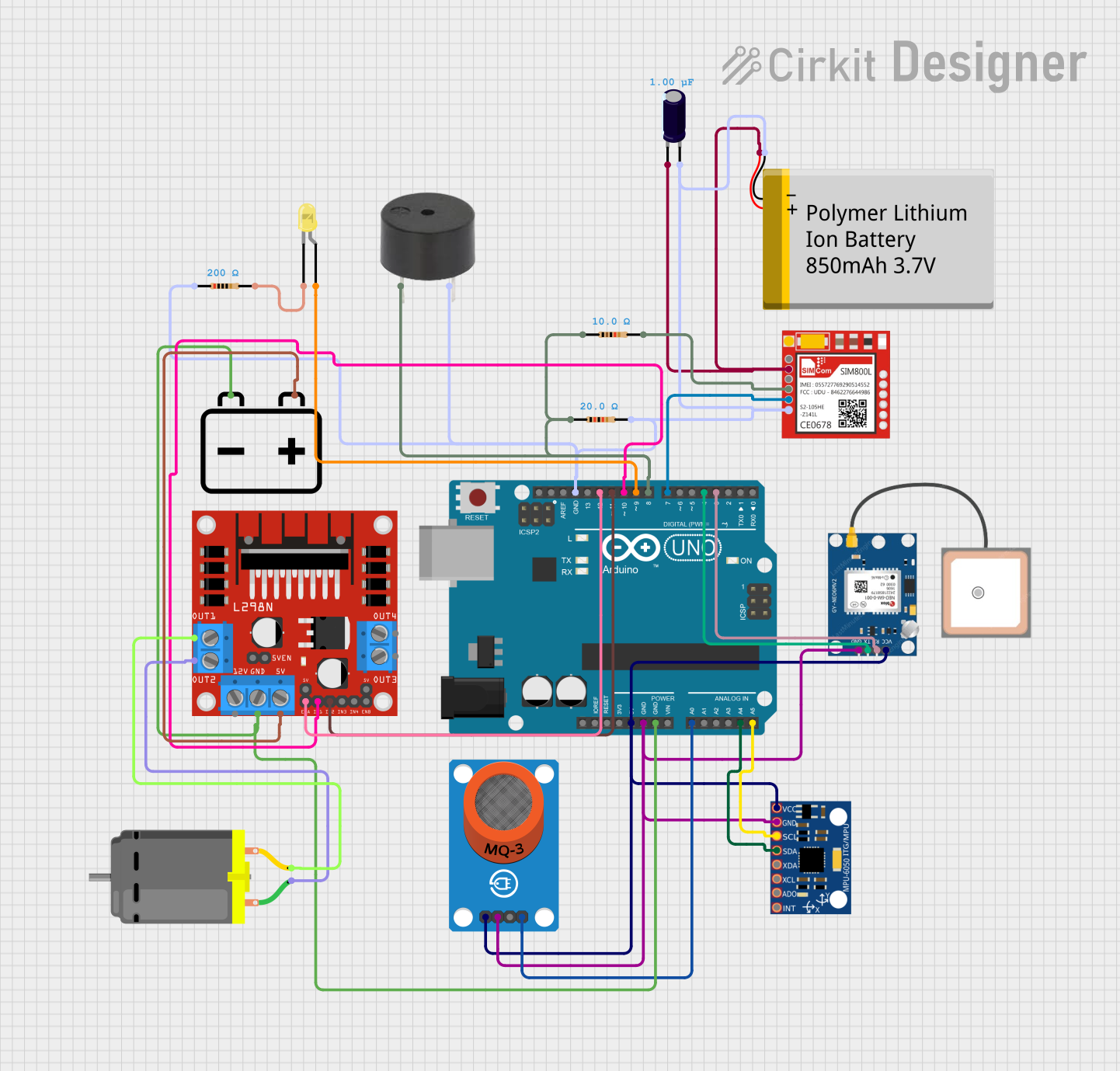
Circuit Documentation
Summary
This document provides a detailed overview of a circuit designed to detect alcohol levels, alert the driver, and send the GPS location via SMS. The circuit utilizes an Arduino UNO microcontroller, various sensors, a GSM module, a GPS module, a motor driver, and other components to achieve its functionality.
Component List
Arduino UNO
- Description: Microcontroller board based on the ATmega328P.
- Pins: UNUSED, IOREF, Reset, 3.3V, 5V, GND, Vin, A0, A1, A2, A3, A4, A5, SCL, SDA, AREF, D13, D12, D11, D10, D9, D8, D7, D6, D5, D4, D3, D2, D1, D0
MQ-3 Breakout
- Description: Alcohol sensor module.
- Pins: VCC, GND, DO, AO
MPU-6050
- Description: 6-axis motion tracking device.
- Pins: VCC, GND, SCL, SDA, XDA, XCL, AD0, INT
Sim800l
- Description: GSM/GPRS module.
- Pins: NET, RST, VCC, RXD, TXD, GND
Polymer Lithium Ion Battery - 850mAh
- Description: Rechargeable battery.
- Pins: GND, VCC
Resistor (10 Ohms)
- Description: Resistor with 10 Ohms resistance.
- Pins: pin1, pin2
Resistor (20 Ohms)
- Description: Resistor with 20 Ohms resistance.
- Pins: pin1, pin2
GPS NEO 6M
- Description: GPS module.
- Pins: VCC, RX, TX, GND
L298N DC motor driver
- Description: Dual H-Bridge motor driver.
- Pins: OUT1, OUT2, 12V, GND, 5V, OUT3, OUT4, 5V-ENA-JMP-I, 5V-ENA-JMP-O, +5V-J1, +5V-J2, ENA, IN1, IN2, IN3, IN4, ENB
12v Battery
- Description: 12V power source.
- Pins: -, +
DC Motor
- Description: DC motor.
- Pins: pin 1, pin 2
Buzzer
- Description: Sound alert device.
- Pins: PIN, GND
LED: Two Pin (yellow)
- Description: Yellow LED.
- Pins: cathode, anode
Resistor (200 Ohms)
- Description: Resistor with 200 Ohms resistance.
- Pins: pin1, pin2
Electrolytic Capacitor
- Description: Capacitor with 0.000001 Farads capacitance.
- Pins: -, +
Wiring Details
Arduino UNO
- 5V connected to VCC of MPU-6050, GPS NEO 6M, and MQ-3 Breakout.
- GND connected to GND of MPU-6050, GPS NEO 6M, MQ-3 Breakout, 12v Battery, L298N DC motor driver, Polymer Lithium Ion Battery, Electrolytic Capacitor, Buzzer, and Sim800l.
- A0 connected to AO of MQ-3 Breakout.
- A4 connected to SDA of MPU-6050.
- A5 connected to SCL of MPU-6050.
- D12 connected to ENA of L298N DC motor driver.
- D11 connected to IN2 of L298N DC motor driver.
- D10 connected to IN1 of L298N DC motor driver.
- D9 connected to anode of LED: Two Pin (yellow).
- D8 connected to PIN of Buzzer.
- D7 connected to TXD of Sim800l.
- D4 connected to TX of GPS NEO 6M.
- D3 connected to RX of GPS NEO 6M.
MQ-3 Breakout
- VCC connected to 5V of Arduino UNO.
- GND connected to GND of Arduino UNO.
- AO connected to A0 of Arduino UNO.
MPU-6050
- VCC connected to 5V of Arduino UNO.
- GND connected to GND of Arduino UNO.
- SDA connected to A4 of Arduino UNO.
- SCL connected to A5 of Arduino UNO.
Sim800l
- GND connected to GND of Arduino UNO.
- TXD connected to D7 of Arduino UNO.
- VCC connected to VCC of Polymer Lithium Ion Battery.
- RXD connected to pin2 of Resistor (10 Ohms).
Polymer Lithium Ion Battery
- GND connected to GND of Arduino UNO.
- VCC connected to - of Electrolytic Capacitor and VCC of Sim800l.
Resistor (10 Ohms)
- pin1 connected to PIN of Buzzer and D8 of Arduino UNO.
- pin2 connected to RXD of Sim800l.
Resistor (20 Ohms)
- pin1 connected to PIN of Buzzer and D8 of Arduino UNO.
- pin2 connected to GND of Polymer Lithium Ion Battery.
GPS NEO 6M
- VCC connected to 5V of Arduino UNO.
- GND connected to GND of Arduino UNO.
- TX connected to D4 of Arduino UNO.
- RX connected to D3 of Arduino UNO.
L298N DC motor driver
- GND connected to GND of Arduino UNO.
- ENA connected to D12 of Arduino UNO.
- IN2 connected to D11 of Arduino UNO.
- IN1 connected to D10 of Arduino UNO.
- OUT1 connected to pin 2 of DC Motor.
- OUT2 connected to pin 1 of DC Motor.
- 5V connected to + of 12v Battery.
12v Battery
- - connected to GND of Arduino UNO.
- + connected to 5V of L298N DC motor driver.
DC Motor
- pin 1 connected to OUT2 of L298N DC motor driver.
- pin 2 connected to OUT1 of L298N DC motor driver.
Buzzer
- PIN connected to pin1 of Resistor (10 Ohms).
- GND connected to GND of Arduino UNO.
LED: Two Pin (yellow)
- anode connected to D9 of Arduino UNO.
- cathode connected to pin2 of Resistor (200 Ohms).
Resistor (200 Ohms)
- pin1 connected to cathode of LED: Two Pin (yellow).
- pin2 connected to GND of Arduino UNO.
Electrolytic Capacitor
- - connected to VCC of Polymer Lithium Ion Battery.
- + connected to GND of Polymer Lithium Ion Battery.
Documented Code
#include <SoftwareSerial.h> // Include for GSM communication
#include <Wire.h>           // Include for I2C communication (if needed)

// Define hardware pins
#define ALCOHOL_PIN      A0  // Analog pin for alcohol sensor
#define BUZZER_PIN       8   // Digital pin for buzzer
#define LED_PIN          9   // Digital pin for LED
#define MOTOR_IN1_PIN    10  // Digital pin for motor driver IN1
#define MOTOR_IN2_PIN    11  // Digital pin for motor driver IN2
#define MOTOR_ENA_PIN    12  // Digital pin for motor driver ENA

// SoftwareSerial for GSM module
SoftwareSerial gsmSerial(7, 6); // RX, TX for GSM module

// Function prototypes
void stopMotor();
void alertDriver();
void sendLocation();
void sendSMS(const char* text);
bool getGPSLocation(double* latitude, double* longitude);

// Setup function
void setup() {
    Serial.begin(9600);         // Initialize serial communication for debugging
    gsmSerial.begin(9600);      // Initialize GSM communication

    // Configure pin modes
    pinMode(ALCOHOL_PIN, INPUT);
    pinMode(BUZZER_PIN, OUTPUT