
Solar-Powered IoT Environmental Monitoring System with GSM Reporting
View and Edit Project In Cirkit Designer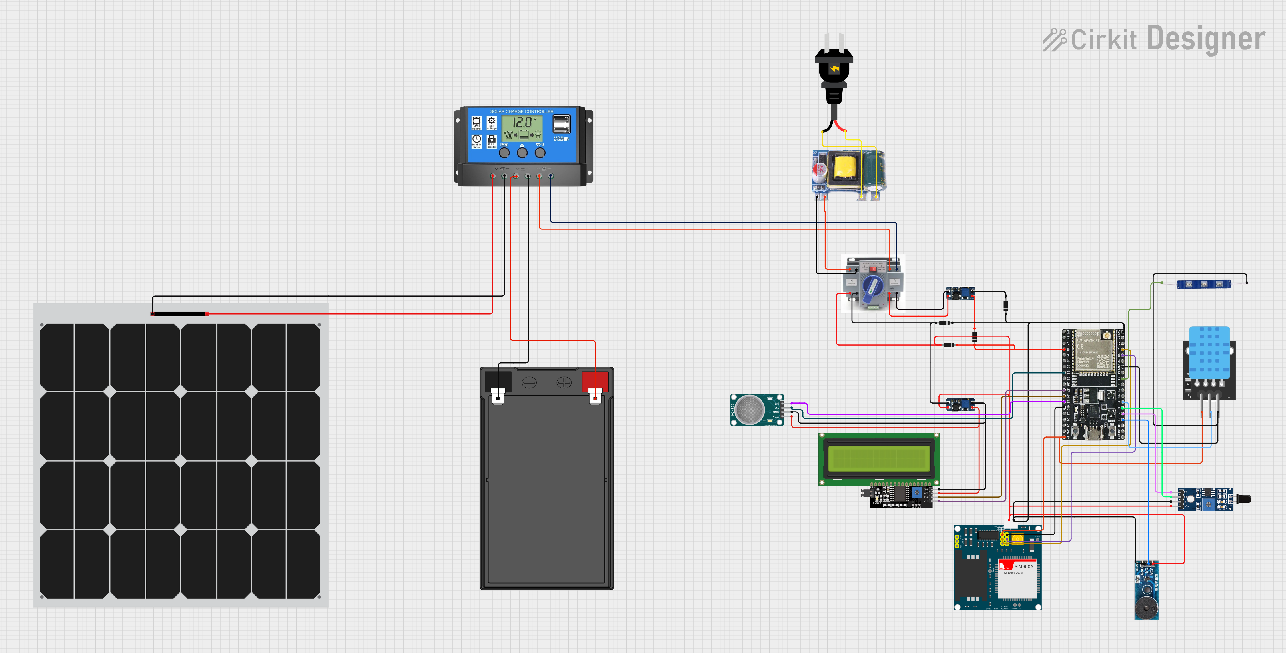
Circuit Documentation
Summary
This circuit is designed to harness solar energy through a Solar Panel, manage power flow and storage with a Solar Charge Controller, and supply power to various components including a SIM900A module, an ESP32 microcontroller, sensors, and a display. The system includes a 12v 7ah Battery for energy storage, an Automatic Transfer Switch (ATS) for power source management, and DC-DC Boost Converters for voltage regulation. Protection diodes are used to prevent reverse current flow. The circuit also features an AC-DC power module to convert mains electricity to a 5V supply when solar power is insufficient. The ESP32 microcontroller is the central processing unit, interfacing with sensors, an LCD display, and the SIM900A module for communication.
Component List
Solar Panel
- A photovoltaic panel that converts sunlight into electrical energy.
12v 7ah Battery
- A rechargeable battery that stores electrical energy for later use.
Solar Charge Controller
- A device that controls the charging of the battery from the solar panel and provides load management.
ATS (Automatic Transfer Switch)
- A switch that automatically transfers power sources between the solar charge controller and the AC-DC power module.
AC source
- An alternating current power source that provides mains electricity.
DC-DC BOOST CONVERTOR
- A device that steps up the voltage from a lower voltage to a higher voltage.
SIM900A
- A GSM/GPRS module for cellular communication.
Diode
- A semiconductor device that allows current to flow in one direction only, used for reverse current protection.
ESP32-WROOM-32UE
- A microcontroller with Wi-Fi and Bluetooth capabilities for controlling and monitoring various functions of the circuit.
MQ-136 SENSOR HYDROGEN SULFIDE GAS
- A sensor for detecting hydrogen sulfide gas concentrations.
TEMP (Temperature Sensor)
- A sensor for measuring temperature.
LCD Display 16x4 I2C
- An alphanumeric display for showing information to the user.
Sensor SHT113 Flame
- A sensor for detecting the presence of flames.
12v Blue LED
- A light-emitting diode that operates at 12 volts, typically used as an indicator.
Buzzer Module
- An audio signaling device.
Mini AC-DC 110V-230V to 5V 700mA Module
- A power supply module that converts AC mains voltage to 5V DC.
Wiring Details
Solar Panel
+connected to Solar Charge Controller Solar Cell +-connected to Solar Charge Controller Solar Cell -
12v 7ah Battery
12v +connected to Solar Charge Controller Battery +12v -connected to Solar Charge Controller Battery -
Solar Charge Controller
Solar Cell +connected to Solar Panel +Solar Cell -connected to Solar Panel -Battery +connected to 12v 7ah Battery 12v +Battery -connected to 12v 7ah Battery 12v -Load +connected to ATS +Load -connected to ATS -
ATS (Automatic Transfer Switch)
+connected to Solar Charge Controller Load +, Mini AC-DC Module 5v, DC-DC BOOST CONVERTOR VIN+, and various components' positive supply lines through diodes and converters.-connected to Solar Charge Controller Load -, Mini AC-DC Module GND, DC-DC BOOST CONVERTOR VIN-, and various components' ground lines.
AC source
-connected to Mini AC-DC 110V-230V to 5V 700mA Module Neutral+connected to Mini AC-DC 110V-230V to 5V 700mA Module Life
DC-DC BOOST CONVERTOR
VIN-connected to ATS - and Diode cathodeVIN+connected to ATS + and various components' positive supply linesVOUT+connected to Diode anode and various components' positive supply linesVOUT-connected to Diode anode and various components' ground lines
SIM900A
GNDconnected to ESP32-WROOM-32UE GND5Vconnected to ESP32-WROOM-32UE 5VVCCconnected to ESP32-WROOM-32UE 5V5VTconnected to ESP32-WROOM-32UE TX5VRconnected to ESP32-WROOM-32UE RX
Diode
cathodeconnected to ESP32-WROOM-32UE GND and various components' ground linesanodeconnected to DC-DC BOOST CONVERTOR VOUT+ and VOUT-
ESP32-WROOM-32UE
GNDconnected to SIM900A GND, various sensors' GND, and 12v Blue LED GND5Vconnected to SIM900A VCC, TEMP 5V, and various sensors' VCCVNconnected to Diode cathode33connected to MQ-136 SENSOR HYDROGEN SULFIDE GAS A027connected to LCD Display 16x4 I2C SCL14connected to LCD Display 16x4 I2C SDA12connected to MQ-136 SENSOR HYDROGEN SULFIDE GAS D0TXconnected to SIM900A 5VTRXconnected to SIM900A 5VR18connected to 12v Blue LED VCC4connected to TEMP D30connected to Sensor SHT113 Flame D02connected to Sensor SHT113 Flame A015connected to Buzzer Module I/O
MQ-136 SENSOR HYDROGEN SULFIDE GAS
VCCconnected to DC-DC BOOST CONVERTOR VOUT+ and LCD Display 16x4 I2C VCCGNDconnected to DC-DC BOOST CONVERTOR VOUT- and LCD Display 16x4 I2C GNDA0connected to ESP32-WROOM-32UE 33D0connected to ESP32-WROOM-32UE 12
TEMP (Temperature Sensor)
5Vconnected to ESP32-WROOM-32UE 5VD3connected to ESP32-WROOM-32UE 4GNDconnected to ESP32-WROOM-32UE GND
LCD Display 16x4 I2C
SCLconnected to ESP32-WROOM-32UE 27SDAconnected to ESP32-WROOM-32UE 14VCCconnected to DC-DC BOOST CONVERTOR VOUT+ and MQ-136 SENSOR HYDROGEN SULFIDE GAS VCCGNDconnected to DC-DC BOOST CONVERTOR VOUT- and MQ-136 SENSOR HYDROGEN SULFIDE GAS GND
Sensor SHT113 Flame
A0connected to ESP32-WROOM-32UE 2D0connected to ESP32-WROOM-32UE 0GNDconnected to ESP32-WROOM-32UE GNDVCCconnected to Buzzer Module Vcc
12v Blue LED
GNDconnected to ESP32-WROOM-32UE GND and TEMP GNDVCCconnected to ESP32-WROOM-32UE 18
Buzzer Module
GNDconnected to Diode cathodeVccconnected to Sensor SHT113 Flame VCCI/Oconnected to ESP32-WROOM-32UE 15
Mini AC-DC 110V-230V to 5V 700mA Module
GNDconnected to ATS -5vconnected to ATS +Neutralconnected to AC source -Lifeconnected to AC source +
Documented Code
No code was provided for the microcontrollers in the circuit. If code becomes available, it should be documented here with explanations for each function and routine, including setup and loop structures, interrupt service routines, and any communication protocols used.