
Circuit Documentation
Summary
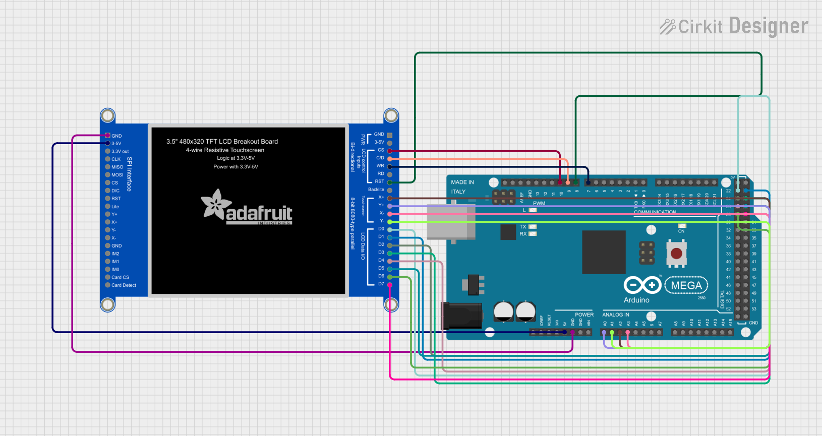
This document provides a detailed overview of a circuit that interfaces an Arduino Mega 2560 microcontroller with a 3.5-inch 480x320 TFT LCD display. The circuit is designed to utilize the display for graphical output while leveraging the processing power of the Arduino Mega 2560. The display is connected to the Arduino through multiple digital and analog pins, allowing for communication and control of the display's functions.
Component List
Arduino Mega 2560
- Description: A microcontroller board based on the ATmega2560, with 54 digital input/output pins, 16 analog inputs, 4 UARTs (hardware serial ports), a 16 MHz crystal oscillator, a USB connection, a power jack, an ICSP header, and a reset button.
- Purpose: Acts as the central processing unit for the circuit, controlling the TFT LCD display and handling data processing and communication.
3.5in 480x320 TFT LCD Display
- Description: A color graphic display with a resolution of 480x320 pixels, capable of displaying detailed images and graphics. It includes a touchscreen interface for user input.
- Purpose: Provides a graphical interface for the user, displaying data and visual feedback from the Arduino Mega 2560.
Wiring Details
Arduino Mega 2560
- 5V: Provides power to the TFT LCD display.
- GND: Common ground with the TFT LCD display.
- D22-D29: Digital pins connected to the LCD data pins (LCD_DATA0_5V to LCD_DATA7_5V) for 8-bit parallel data transfer.
- A0-A3: Analog pins connected to the LCD touch screen interface (LCD_Y+, LCD_X+, LCD_Y-, LCD_X-).
- D7-D10: Digital pins connected to the LCD control pins (WR/SPI CLK, RST, C/D, CS).
3.5in 480x320 TFT LCD Display
- +5V: Receives power from the Arduino Mega 2560.
- GND: Connected to the common ground with the Arduino Mega 2560.
- LCD_DATA0_5V - LCD_DATA7_5V: Connected to digital pins D22-D29 on the Arduino Mega 2560 for parallel data communication.
- LCD_Y+, LCD_X+, LCD_Y-, LCD_X-: Touchscreen interface connected to analog pins A0-A3 on the Arduino Mega 2560.
- RST, WR/SPI CLK, C/D, CS: Control pins connected to digital pins D8-D10 on the Arduino Mega 2560.
Documented Code
#include <Adafruit_GFX.h>
#include <Adafruit_ILI9341.h>

// Configura los pines de tu pantalla TFT según las conexiones físicas
#define TFT_CS     10  // Chip Select
#define TFT_RST    8   // Reset
#define TFT_DC     9   // Data/Command

// Inicializa la pantalla TFT
Adafruit_ILI9341 tft = Adafruit_ILI9341(TFT_CS, TFT_DC, TFT_RST);

// ... (El resto del código permanece igual)

void setup() {
  // ... (El resto del código de setup permanece igual)

  // Configura los pines de control de la pantalla como salida
  pinMode(TFT_CS, OUTPUT);
  pinMode(TFT_RST, OUTPUT);
  pinMode(TFT_DC, OUTPUT);

  // ... (El resto del código de setup permanece igual)
}
File Name: sketch.ino
Description: This code snippet initializes the Adafruit ILI9341 library and configures the necessary pins for communication with the TFT LCD display. The TFT_CS, TFT_RST, and TFT_DC pins are defined according to the physical connections and set as outputs in the setup() function. The rest of the code, which is not shown here, would typically include the initialization of the display and the main program logic to interact with the display.