
Arduino UNO-Based Smart AC Bulb Control with GSM and Current Sensing
View and Edit Project In Cirkit Designer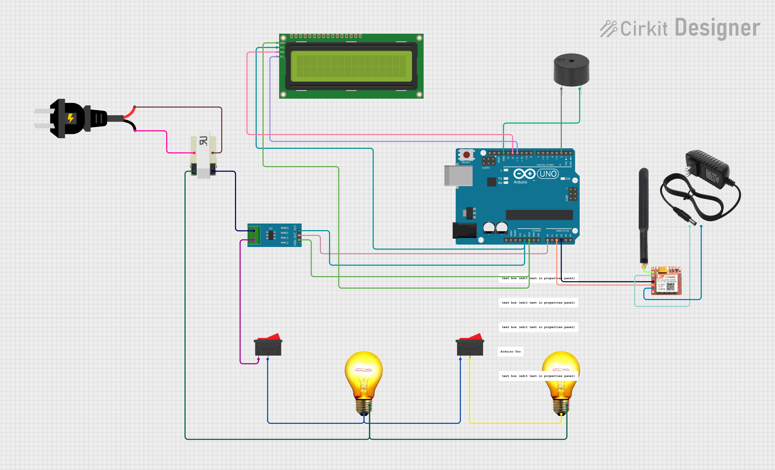
Circuit Documentation
Summary
This circuit involves an Arduino UNO microcontroller interfacing with various components including a current sensor, an I2C LCD display, a buzzer, a SIM800L module, a 4G antenna, AC bulbs, a transformer, rocker switches, a 12V power supply, and an AC source. The Arduino UNO is used to control and monitor the components, while the SIM800L module provides GSM communication capabilities.
Component List
Arduino UNO
- Description: A microcontroller board based on the ATmega328P.
- Pins: UNUSED, IOREF, Reset, 3.3V, 5V, GND, Vin, A0, A1, A2, A3, A4, A5, SCL, SDA, AREF, D13, D12, D11, D10, D9, D8, D7, D6, D5, D4, D3, D2, D1, D0
AC Bulb
- Description: Standard AC bulb.
- Pins: P, N
Transformer
- Description: A device that transfers electrical energy between two or more circuits through electromagnetic induction.
- Pins: 4, 1, 2, 3
16x2 I2C LCD
- Description: A 16x2 character LCD display with I2C interface.
- Pins: GND, VCC, SDA, SCL
Buzzer
- Description: An audio signaling device.
- Pins: PIN, GND
SIM800L
- Description: A GSM/GPRS module for communication.
- Pins: NFT, RING, VCC, DTR, RST, MIC +, RXD, MIC-, TXD, SPK+, GND, SPK-
4G Antenna
- Description: An antenna for 4G communication.
- Pins: Connection
Rocker Switch
- Description: A switch that rocks back and forth to open or close a circuit.
- Pins: 1, 2
Current Sensor 5A
- Description: A sensor to measure current up to 5A.
- Pins: 1, 2, GND, OUT, VCC
12V Power Supply
- Description: A power supply providing 12V output.
- Pins: +, -
AC Source
- Description: An AC power source.
- Pins: +, -
Wiring Details
Arduino UNO
- 5V connected to VCC of Current Sensor 5A and 16x2 I2C LCD.
- GND connected to GND of Current Sensor 5A, 16x2 I2C LCD, and Buzzer.
- A0 connected to OUT of Current Sensor 5A.
- A2 connected to TXD of SIM800L.
- A3 connected to RXD of SIM800L.
- D12 connected to SDA of 16x2 I2C LCD.
- D11 connected to SCL of 16x2 I2C LCD.
- D2 connected to PIN of Buzzer.
AC Bulb
- P of one AC Bulb connected to 2 of Rocker Switch.
- N of one AC Bulb connected to 2 of Transformer.
- P of another AC Bulb connected to 2 of another Rocker Switch.
- N of another AC Bulb connected to 2 of Transformer.
Transformer
- 2 connected to N of AC Bulbs.
- 4 connected to + of AC Source.
- 1 connected to - of AC Source.
- 3 connected to 1 of Current Sensor 5A.
16x2 I2C LCD
- VCC connected to 5V of Arduino UNO.
- GND connected to GND of Arduino UNO.
- SDA connected to D12 of Arduino UNO.
- SCL connected to D11 of Arduino UNO.
Buzzer
- PIN connected to D2 of Arduino UNO.
- GND connected to GND of Arduino UNO.
SIM800L
- TXD connected to A2 of Arduino UNO.
- RXD connected to A3 of Arduino UNO.
- VCC connected to + of 12V Power Supply.
- GND connected to - of 12V Power Supply.
- NFT connected to Connection of 4G Antenna.
4G Antenna
- Connection connected to NFT of SIM800L.
Rocker Switch
- 2 of one Rocker Switch connected to 1 of another Rocker Switch and P of AC Bulb.
- 2 of another Rocker Switch connected to P of another AC Bulb.
Current Sensor 5A
- VCC connected to 5V of Arduino UNO.
- GND connected to GND of Arduino UNO.
- OUT connected to A0 of Arduino UNO.
- 1 connected to 3 of Transformer.
- 2 connected to 1 of Rocker Switch.
12V Power Supply
- + connected to VCC of SIM800L.
- - connected to GND of SIM800L.
AC Source
- + connected to 4 of Transformer.
- - connected to 1 of Transformer.
Code Documentation
Arduino UNO Code
sketch.ino
void setup() {
  // put your setup code here, to run once:

}

void loop() {
  // put your main code here, to run repeatedly:

}
documentation.txt