Cirkit Designer
Your all-in-one circuit design IDE
Home /
Project Documentation
Arduino 101 Based Access Control System with RFID and Keypad

Circuit Documentation
Summary
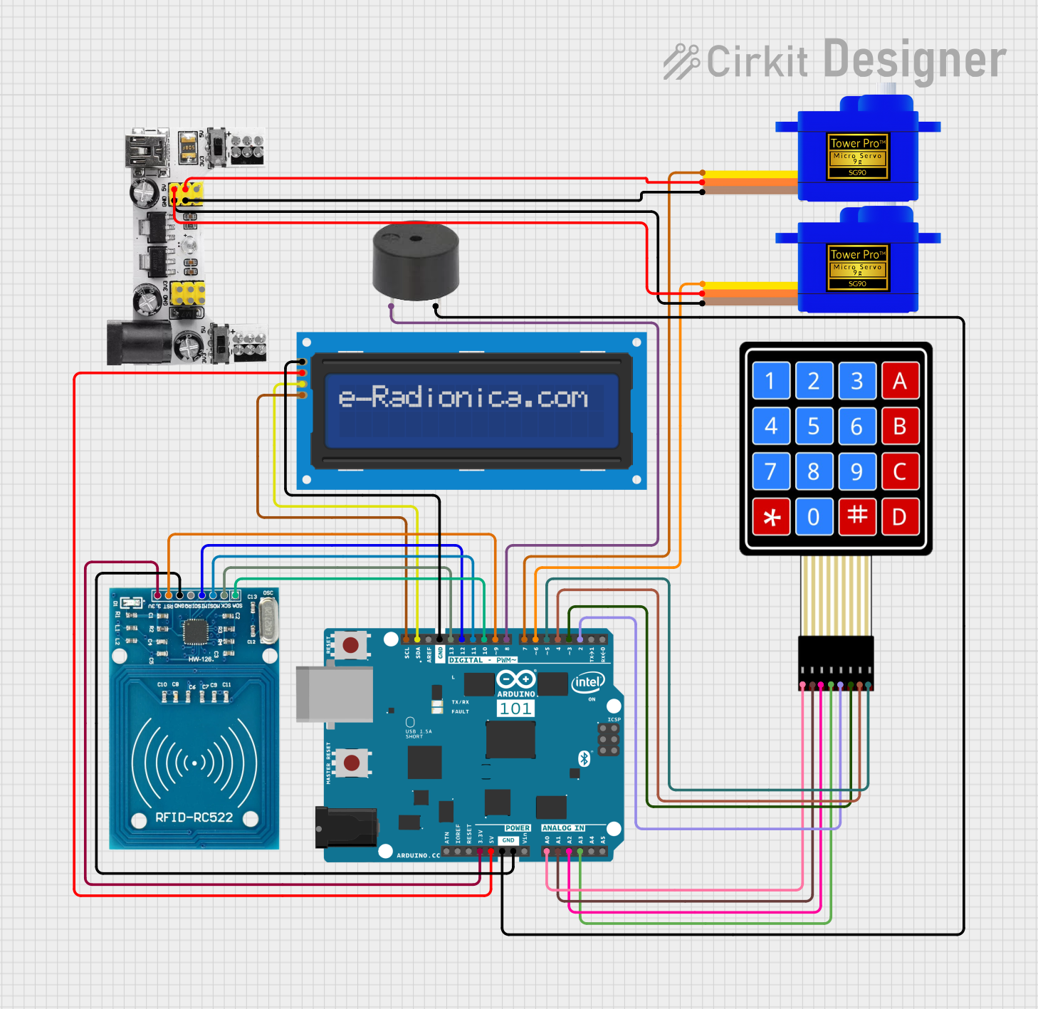
The circuit is designed to interface an Arduino 101 with various peripherals including an LCD screen, an RFID reader, a buzzer, a keypad, and two servomotors. The Arduino 101 serves as the central processing unit, controlling the input and output devices. The LCD screen is used for displaying information, the RFID reader for scanning RFID tags, the buzzer for audio feedback, the keypad for user input, and the servomotors for physical movement.
Component List
Arduino 101
- Microcontroller board based on the Intel Curie
- Provides I/O pins for interfacing with other components
- Operates at 3.3V and 5V logic levels
LCD screen 16x2 I2C
- Alphanumeric liquid crystal display
- 16 characters by 2 lines
- I2C communication interface
4X4 Membrane Matrix Keypad
- 16-button keypad arranged in a 4x4 matrix
- Provides user input capability
RFID-RC522
- RFID reader/writer module
- Operates at 13.56 MHz
- SPI communication interface
Servomotor SG90 (2 units)
- Small and lightweight servo motor
- Provides precise control of angular position
Breadboard Power Module (3.3/5V)
- Provides regulated 3.3V and 5V power supply
- Powers components on the breadboard
Buzzer
- Generates audio signals for alerts or notifications
Wiring Details
Arduino 101
A5/SCLconnected to LCD screen SCLA4/SDAconnected to LCD screen SDAGNDconnected to LCD screen GND, RFID-RC522 GND, buzzer GNDD13/SCKconnected to RFID-RC522 SCKD12/MISOconnected to RFID-RC522 MISOD11 PWM/MOSIconnected to RFID-RC522 MOSID10 PWM/SSconnected to RFID-RC522 SDAD9 PWMconnected to RFID-RC522 RSTD8connected to buzzer PIND7connected to Servomotor SG90 (instance 1) SIGD6 PWMconnected to Servomotor SG90 (instance 2) SIGD5 PWMtoD2connected to Keypad C4 to C1 respectively3V3connected to RFID-RC522 VCC (3.3V)5Vconnected to LCD screen VCCA0toA3connected to Keypad R1 to R4 respectively
LCD screen 16x2 I2C
SCLconnected to Arduino 101 A5/SCLSDAconnected to Arduino 101 A4/SDAVCCconnected to Arduino 101 5VGNDconnected to Arduino 101 GND
4X4 Membrane Matrix Keypad
R1toR4connected to Arduino 101 A0 to A3 respectivelyC1toC4connected to Arduino 101 D2 to D5 PWM respectively
RFID-RC522
VCC (3.3V)connected to Arduino 101 3V3RSTconnected to Arduino 101 D9 PWMGNDconnected to Arduino 101 GNDIRQnot connectedMISOconnected to Arduino 101 D12/MISOMOSIconnected to Arduino 101 D11 PWM/MOSISCKconnected to Arduino 101 D13/SCKSDAconnected to Arduino 101 D10 PWM/SS
Servomotor SG90 (2 units)
SIGof each servomotor connected to Arduino 101 D7 and D6 PWM respectivelyVCCof each servomotor connected to Breadboard Power Module VCC (5V)GNDof each servomotor connected to Breadboard Power Module GND
Breadboard Power Module (3.3/5V)
VCC (5V)connected to both Servomotor SG90 VCCGNDconnected to both Servomotor SG90 GND
Buzzer
PINconnected to Arduino 101 D8GNDconnected to Arduino 101 GND
Documented Code
No code has been provided for the microcontrollers in the circuit. The code would typically include initialization of the peripherals, the main control loop, and functions to handle input/output operations with the connected devices.