Cirkit Designer
Your all-in-one circuit design IDE
Home /
Project Documentation
Arduino UNO-Based Smart Weather Station with Wi-Fi Connectivity
Circuit Documentation
Summary
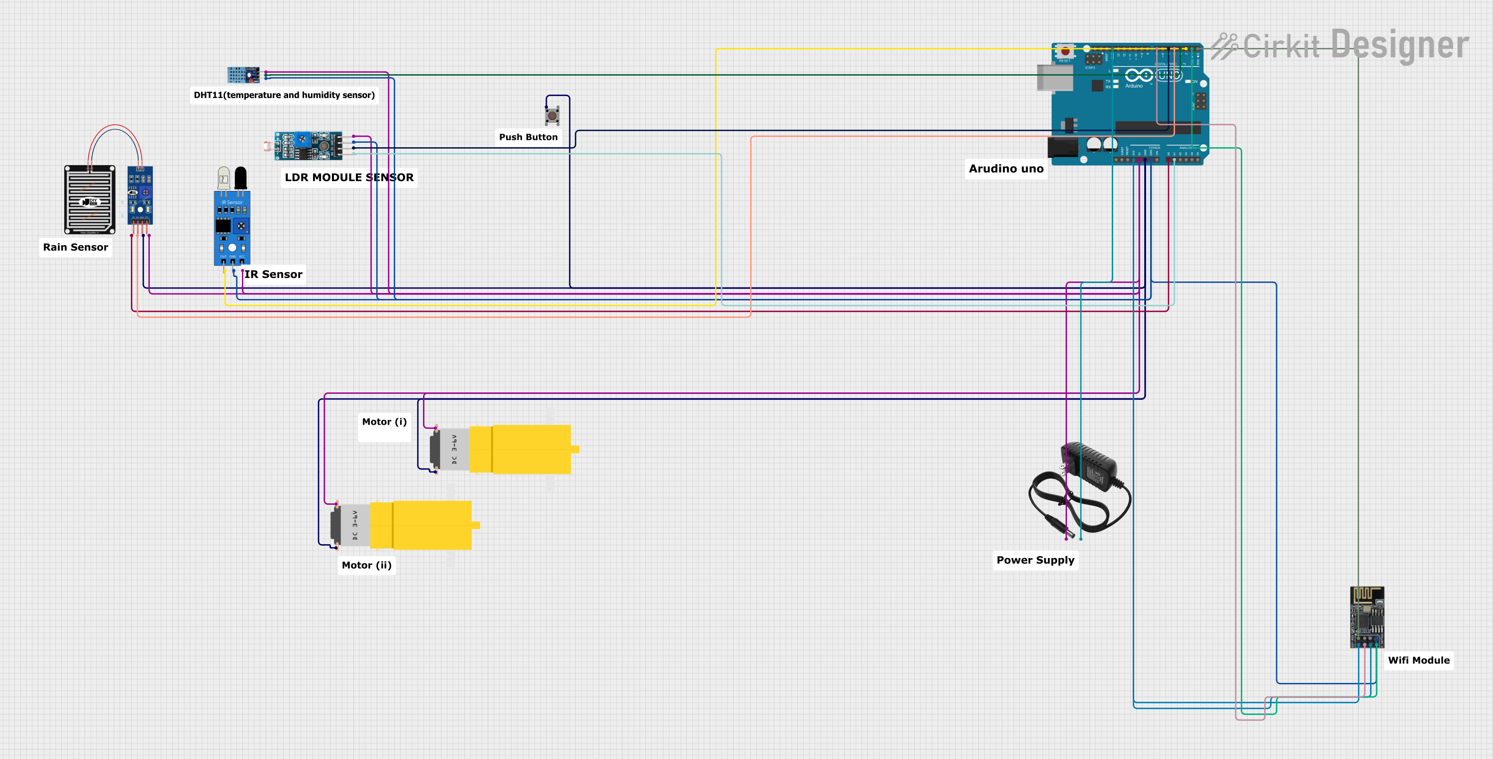
This document provides a detailed overview of a circuit that includes various sensors, a WiFi module, motors, and an Arduino UNO microcontroller. The circuit is designed to interface with multiple sensors and actuators, providing a comprehensive setup for a variety of applications.
Component List
Pushbutton
- Description: A simple pushbutton switch.
- Pins: Pin 3 (out), Pin 4 (out), Pin 1 (in), Pin 2 (in)
IR Sensor
- Description: An infrared sensor used for detecting objects or measuring distance.
- Pins: out, gnd, vcc
DHT 11
- Description: A digital temperature and humidity sensor.
- Pins: VCC, GND, DATA
Rain Sensor
- Description: A sensor used to detect the presence of rain.
- Pins: AO, DO, GRD, VCC
WiFi Module ESP8266-01
- Description: A WiFi module used for wireless communication.
- Pins: RX, GPIO0, GPIO2, GND, +3V3, Reset, CH-PD Chip power down, TX
Motor (Yellow Gear Motor)
- Description: A hobby motor with a gearbox.
- Pins: vcc, GND
12V Power Supply
- Description: A power supply providing 12V output.
- Pins: +, -
Arduino UNO
- Description: A microcontroller board based on the ATmega328P.
- Pins: UNUSED, IOREF, Reset, 3.3V, 5V, GND, Vin, A0, A1, A2, A3, A4, A5, SCL, SDA, AREF, D13, D12, D11, D10, D9, D8, D7, D6, D5, D4, D3, D2, D1, D0
Module LDR
- Description: A light-dependent resistor module.
- Pins: VCC, GND, DO, AO
Wiring Details
Pushbutton
- Pin 1 (in): Connected to GND of Arduino UNO
- Pin 2 (in): Not connected
- Pin 3 (out): Not connected
- Pin 4 (out): Not connected
IR Sensor
- vcc: Connected to 5V of Arduino UNO
- gnd: Connected to GND of Arduino UNO
- out: Connected to D2 of Arduino UNO
DHT 11
- VCC: Connected to 5V of Arduino UNO
- GND: Connected to GND of Arduino UNO
- DATA: Connected to D3 of Arduino UNO
Rain Sensor
- VCC: Connected to 5V of Arduino UNO
- GRD: Connected to GND of Arduino UNO
- AO: Connected to A0 of Arduino UNO
- DO: Connected to D4 of Arduino UNO
WiFi Module ESP8266-01
- +3V3: Connected to 3.3V of Arduino UNO
- CH-PD Chip power down: Connected to 3.3V of Arduino UNO
- GND: Connected to GND of Arduino UNO
- RX: Connected to D0 of Arduino UNO
- TX: Connected to D1 of Arduino UNO
- Reset: Connected to D7 of Arduino UNO
- GPIO0: Not connected
- GPIO2: Not connected
Motor (Yellow Gear Motor)
- vcc: Connected to 5V of Arduino UNO
- GND: Connected to GND of Arduino UNO
12V Power Supply
- +: Connected to 5V of Arduino UNO
- -: Connected to GND of Arduino UNO
Arduino UNO
- 3.3V: Connected to +3V3 and CH-PD Chip power down of WiFi module ESP8266-01
- 5V: Connected to VCC of Rain Sensor, Motor (Yellow Gear Motor), Module LDR, DHT 11, and IR Sensor
- GND: Connected to GND of Rain Sensor, Motor (Yellow Gear Motor), Module LDR, DHT 11, WiFi module ESP8266-01, IR Sensor, and 12V Power Supply
- A0: Connected to AO of Rain Sensor
- A1: Connected to AO of Module LDR
- D0: Connected to RX of WiFi module ESP8266-01
- D1: Connected to TX of WiFi module ESP8266-01
- D2: Connected to out of IR Sensor
- D3: Connected to DATA of DHT 11
- D4: Connected to DO of Rain Sensor
- D5: Connected to DO of Module LDR
- D7: Connected to Reset of WiFi module ESP8266-01
Module LDR
- VCC: Connected to 5V of Arduino UNO
- GND: Connected to GND of Arduino UNO
- DO: Connected to D5 of Arduino UNO
- AO: Connected to A1 of Arduino UNO
Documented Code
Arduino UNO Code
void setup() {
  // put your setup code here, to run once:

}

void loop() {
  // put your main code here, to run repeatedly:

}
This concludes the documentation for the circuit. Each component is described along with its wiring details, and the code for the Arduino UNO is provided.