
Battery-Powered ESP32 Data Logger with Oscilloscope Monitoring
View and Edit Project In Cirkit Designer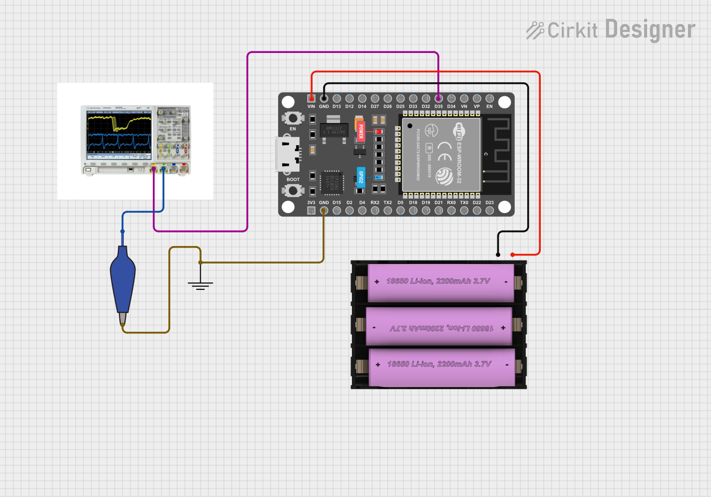
Circuit Documentation
Summary
This document provides a detailed overview of a circuit involving an ESP32 microcontroller, a mixed signal oscilloscope, a ground connection, an alligator clip cable, and a 7V battery. The circuit is designed to power the ESP32 and monitor one of its pins using the oscilloscope.
Component List
ESP 32 DEVKIT V1 (30 pins)
- Description: A development board featuring the ESP32 microcontroller with 30 pins.
- Pins: EN, VP, VN, D34, D35, D32, D33, D25, D26, D27, D14, D12, D13, GND, VIN, 3V3, D15, D2, D4, RX2, TX2, D5, D18, D19, D21, RX0, TX0, D22, D23
Mixed Signal Oscilloscope
- Description: An oscilloscope capable of measuring both analog and digital signals.
- Pins: 1, 2, 3, 4
GND
- Description: A ground connection point.
- Pins: GND
12978-alligator_clip_cable_half-blue
- Description: An alligator clip cable used for making temporary electrical connections.
- Pins: Pin, Alligator
Set battery (7v)
- Description: A 7V battery used to power the circuit.
- Pins: +, -
Wiring Details
ESP 32 DEVKIT V1 (30 pins)
- D35 is connected to Pin 1 of the Mixed Signal Oscilloscope.
- GND is connected to the negative terminal (-) of the Set battery (7v).
- VIN is connected to the positive terminal (+) of the Set battery (7v).
- GND is also connected to the Alligator pin of the 12978-alligator_clip_cable_half-blue.
Mixed Signal Oscilloscope
- Pin 1 is connected to D35 of the ESP 32 DEVKIT V1 (30 pins).
- Pin 2 is connected to the Pin of the 12978-alligator_clip_cable_half-blue.
GND
- GND is connected to the Alligator pin of the 12978-alligator_clip_cable_half-blue and to GND of the ESP 32 DEVKIT V1 (30 pins).
12978-alligator_clip_cable_half-blue
- Alligator is connected to GND of the ESP 32 DEVKIT V1 (30 pins) and to GND.
- Pin is connected to Pin 2 of the Mixed Signal Oscilloscope.
Set battery (7v)
- - is connected to GND of the ESP 32 DEVKIT V1 (30 pins).
- + is connected to VIN of the ESP 32 DEVKIT V1 (30 pins).
Code
There is no code provided for this circuit.