
ESP32-Controlled Obstacle Avoidance Robot with Ultrasonic Sensor and Servo Motor
View and Edit Project In Cirkit Designer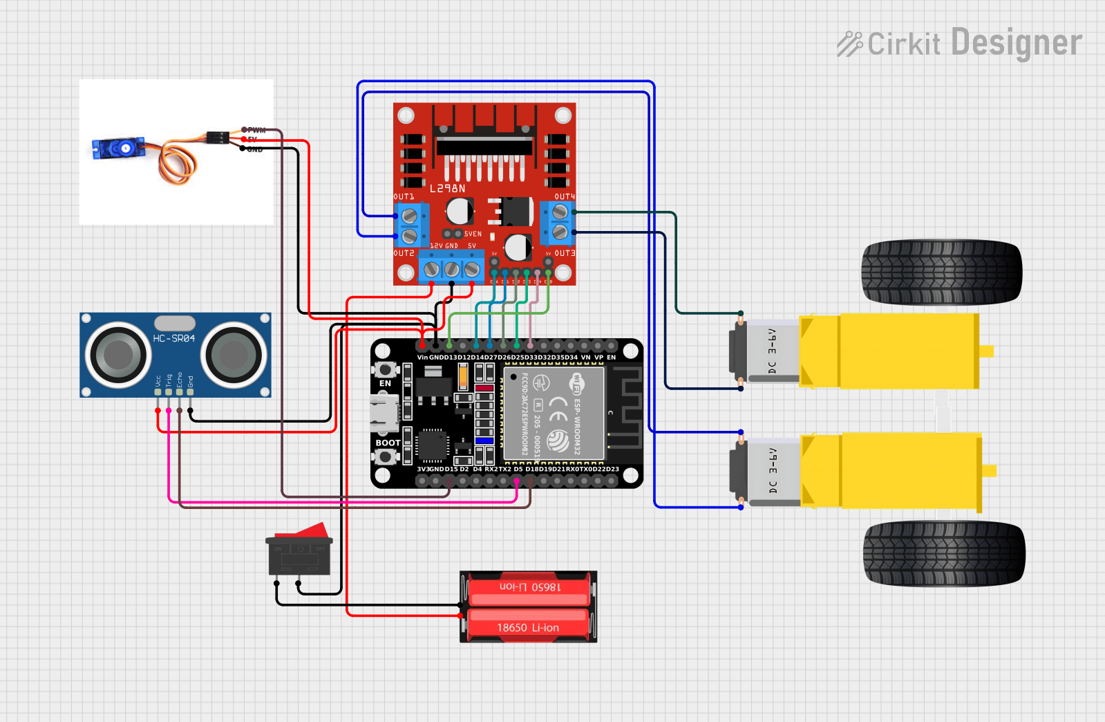
Circuit Documentation
Summary
This circuit is designed to control a mobile robot equipped with DC gearmotors for movement, an ultrasonic sensor for distance measurement, and a servo motor for directional scanning. The ESP32 microcontroller serves as the brain of the robot, interfacing with the L298N motor driver to control the gearmotors, reading distance data from the HC-SR04 ultrasonic sensor, and controlling the position of the SG90 servo motor. Power is supplied by a 18650 Li-Ion battery, and a rocker switch is used to turn the circuit on and off.
Component List
ESP32 (30 pin)
- Microcontroller with WiFi and Bluetooth capabilities.
- It has a variety of digital I/O pins and supports serial communication.
Gearmotor DC Wheels (Right and Left)
- DC motors with gear reduction used for driving the wheels of the robot.
SG90 Servo Motor
- A small and lightweight servo motor used for precise angular positioning.
L298N DC Motor Driver
- A dual H-bridge motor driver that can drive two DC motors or one stepper motor.
HC-SR04 Ultrasonic Sensor
- An ultrasonic distance sensor that can measure distances by emitting ultrasonic waves.
18650 Li-Ion Battery
- A rechargeable battery that provides power to the circuit.
Rocker Switch
- A simple on/off switch to control the power flow to the circuit.
Wiring Details
ESP32 (30 pin)
D33connected to L298N DC motor driverIN4D25connected to L298N DC motor driverIN3D26connected to L298N DC motor driverIN2D27connected to L298N DC motor driverIN1D14connected to L298N DC motor driverENAD13connected to L298N DC motor driverENBGNDconnected to common ground netVinconnected to 5V power netD18connected to HC-SR04 Ultrasonic SensorECHOD5connected to HC-SR04 Ultrasonic SensorTRIGD15connected to SG90 Servo MotorPWM
Gearmotor DC Wheels Right
PIN1connected to L298N DC motor driverOUT4PIN2connected to L298N DC motor driverOUT3
Gearmotor DC Wheels Left
PIN1connected to L298N DC motor driverOUT1PIN2connected to L298N DC motor driverOUT2
SG90 Servo Motor
PWMconnected to ESP32D155Vconnected to 5V power netGNDconnected to common ground net
L298N DC Motor Driver
IN1-IN4connected to ESP32D27,D26,D25,D33ENA,ENBconnected to ESP32D14,D13GNDconnected to common ground net5Vconnected to 5V power netOUT1-OUT4connected to Gearmotor DC Wheels12Vconnected to 18650 Li-Ion BatteryPositive
HC-SR04 Ultrasonic Sensor
VCCconnected to 5V power netTRIGconnected to ESP32D5ECHOconnected to ESP32D18GNDconnected to common ground net
18650 Li-Ion Battery
Positiveconnected to L298N DC motor driver12VNegativeconnected to Rocker Switch1
Rocker Switch
1connected to 18650 Li-Ion BatteryNegative2connected to common ground net
Documented Code
#include <Servo.h>

// Pin Definitions
#define trigPin 5
#define echoPin 18
#define ENA 14
#define ENB 13
#define IN1 27
#define IN2 26
#define IN3 25
#define IN4 33
#define servoPin 15

Servo myServo;

// Variables for distance measurement
long duration;
int distance;
int rightDistance, leftDistance;

// Function to calculate distance
int getDistance() {
  digitalWrite(trigPin, LOW);
  delayMicroseconds(2);
  digitalWrite(trigPin, HIGH);
  delayMicroseconds(10);
  digitalWrite(trigPin, LOW);
  duration = pulseIn(echoPin, HIGH);
  distance = duration * 0.034 / 2;
  return distance;
}

// Motor control functions
void moveForward() {
  digitalWrite(IN1, HIGH);
  digitalWrite(IN2, LOW);
  digitalWrite(IN3, HIGH);
  digitalWrite(IN4, LOW);
  analogWrite(ENA, 250); // Adjust speed using PWM (0-255)
  analogWrite(ENB, 250); // Adjust speed using PWM (0-255)
}

void moveBackward() {
  digitalWrite(IN1, LOW);
  digitalWrite(IN2, HIGH);
  digitalWrite(IN3, LOW);
  digitalWrite(IN4, HIGH);
  analogWrite(ENA, 250); // Adjust speed using PWM
  analogWrite(ENB, 250); // Adjust speed using PWM
}

void stopCar() {
  digitalWrite(IN1, LOW);
  digitalWrite(IN2, LOW);
  digitalWrite(IN3, LOW);
  digitalWrite(IN4, LOW);
}

void turnLeft() {
  digitalWrite(IN1, LOW);
  digitalWrite(IN2, HIGH);
  digitalWrite(IN3, HIGH);
  digitalWrite(IN4, LOW);
  analogWrite(ENA, 150); // Adjust speed for turning
  analogWrite(ENB, 150); // Adjust speed for turning
}

void turnRight() {
  digitalWrite(IN1, HIGH);
  digitalWrite(IN2, LOW);
  digitalWrite(IN3, LOW);
  digitalWrite(IN4, HIGH);
  analogWrite(ENA, 150); // Adjust speed for turning
  analogWrite(ENB, 150); // Adjust speed for turning
}

void setup() {
  // Setup pins
  pinMode(trigPin, OUTPUT);
  pinMode(echoPin, INPUT);
  pinMode(IN1, OUTPUT);
  pinMode(IN2, OUTPUT);
  pinMode(IN3, OUTPUT);
  pinMode(IN4, OUTPUT);
  pinMode(ENA, OUTPUT);
  pinMode(ENB, OUTPUT);

  // Servo setup
  myServo.attach(servoPin);
  myServo.write(90); // Start servo at center position

  Serial.begin(9600);
}

void loop() {
  // Scan forward
  myServo.write(90); // Center position (looking straight ahead)
  delay(500);
  int frontDistance = getDistance();

  // If an obstacle is closer than 20 cm
  if (frontDistance < 20) {
    stopCar();
    delay(1000); // Pause to make a decision

    // Scan left side
    myServo.write(0); // Turn servo to the left
    delay(500);
    leftDistance = getDistance();

    // Scan right side
    myServo.write(180); // Turn servo to the right
    delay(500);
    rightDistance = getDistance();

    // Decide direction based on the distances
    if (leftDistance > rightDistance) {
      turnLeft();
      delay(1000); // Adjust the delay to control turning duration
    } else {
      turnRight();
      delay(1000); // Adjust the delay to control turning duration
    }

    stopCar(); // Stop after turning
    delay(1000); // Brief pause before moving forward again
  } else {
    moveForward(); // Continue moving forward if the path is clear
  }

  delay(200); // Short delay before next loop iteration
}
This code is designed to be uploaded to the ESP32 microcontroller. It initializes the pins and sets up the servo motor, then enters a loop where it continuously checks for obstacles using the ultrasonic sensor. If an obstacle is detected, the robot will stop, scan the area with the servo motor, and then decide which direction to turn based on the distance measurements. The robot will then turn in the chosen direction, stop, and proceed to move forward again if the path is clear.