Cirkit Designer
Your all-in-one circuit design IDE
Home /
Project Documentation
Battery-Powered LDR-Controlled LED Light System
Circuit Documentation
Summary
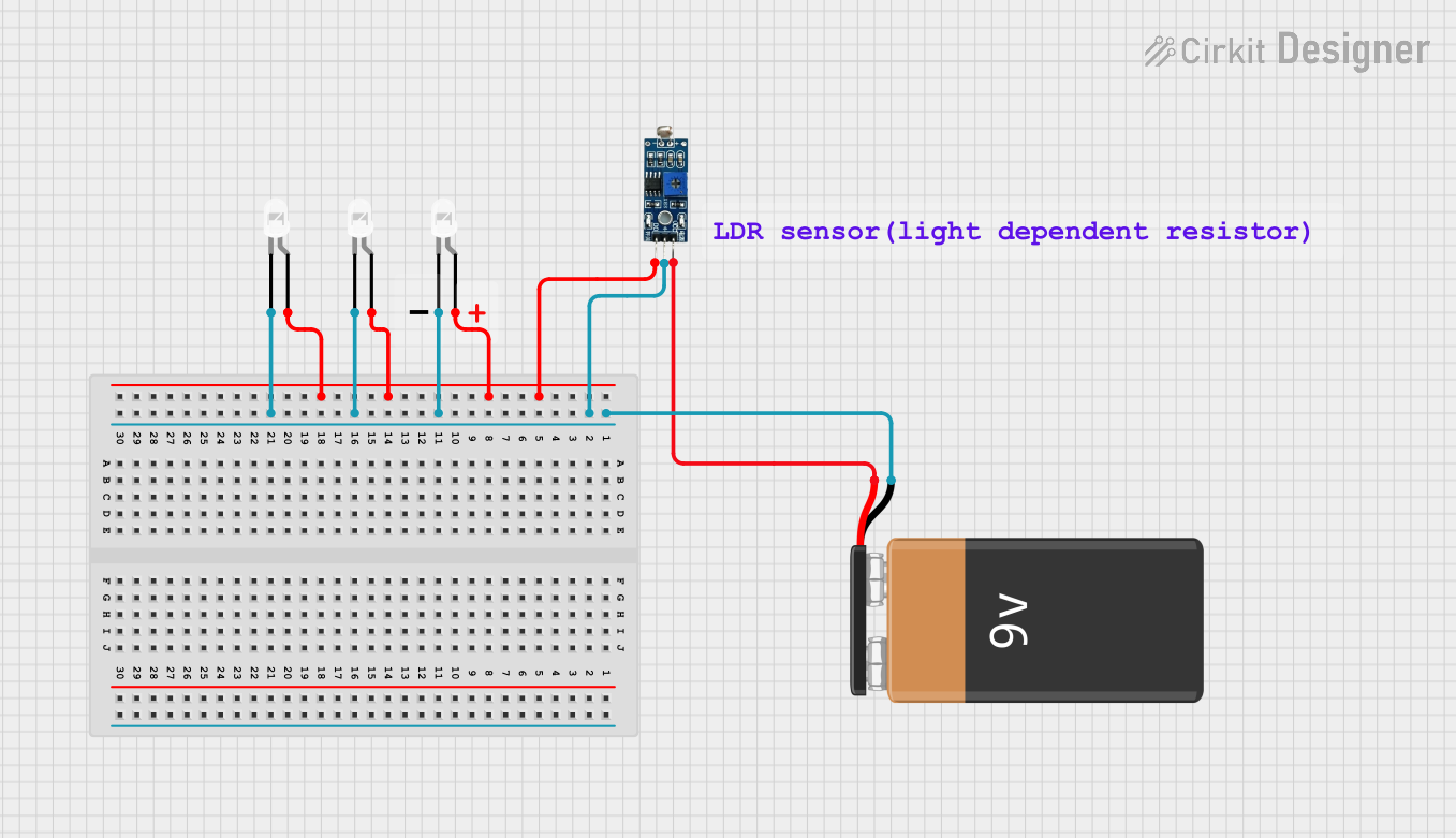
This circuit is designed to control three white LEDs using an LDR (Light Dependent Resistor) module. The LEDs will light up based on the output of the LDR module, which is powered by a 9V battery. The LDR module detects the ambient light level and controls the LEDs accordingly.
Component List
LDR Module 3 pin
- Pins: VCC, GND, DO
- Description: A light-dependent resistor module that outputs a digital signal based on the ambient light level.
- Purpose in Circuit: To detect ambient light and control the LEDs.
9V Battery
- Pins: +, -
- Description: A 9V power source.
- Purpose in Circuit: To provide power to the LDR module and LEDs.
LED: Two Pin (white)
- Pins: anode, cathode
- Description: A white LED with two pins.
- Purpose in Circuit: To emit light when powered.
Comment
- Description: Placeholder for comments or notes in the circuit.
- Purpose in Circuit: Not used in the electrical connections.
Wiring Details
LDR Module 3 pin
- VCC is connected to the + pin of the 9V Battery.
- GND is connected to the - pin of the 9V Battery.
- DO is connected to the anode pins of all three LEDs.
9V Battery
- + is connected to the VCC pin of the LDR Module 3 pin.
- - is connected to the GND pin of the LDR Module 3 pin and the cathode pins of all three LEDs.
LED: Two Pin (white)
- anode of each LED is connected to the DO pin of the LDR Module 3 pin.
- cathode of each LED is connected to the - pin of the 9V Battery.
Documented Code
There is no microcontroller code provided for this circuit.