
Arduino UNO and ESP32 Based Temperature Monitoring and Access Control System
View and Edit Project In Cirkit Designer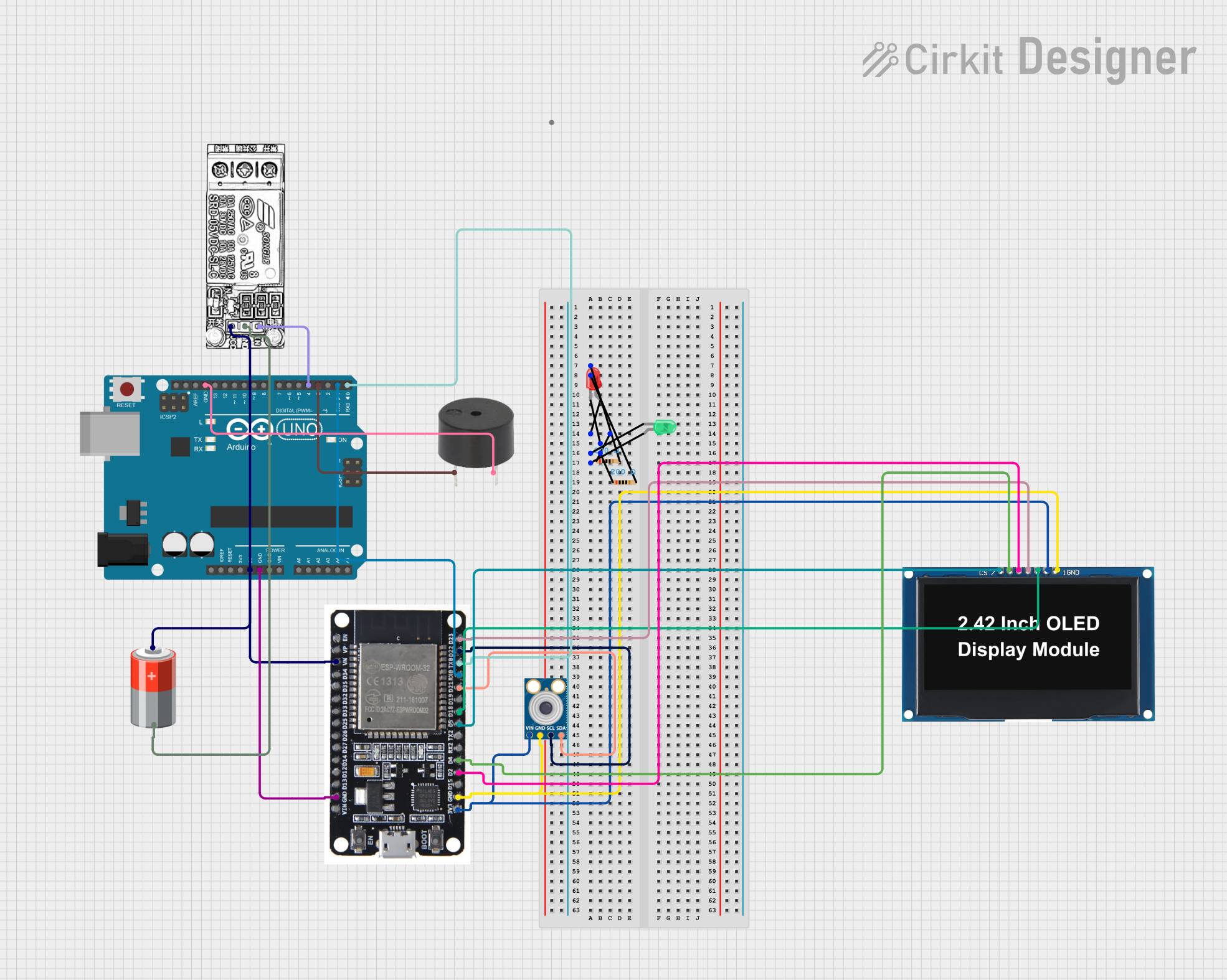
Circuit Documentation
Summary of the Circuit
This circuit integrates an Arduino UNO and an ESP32 microcontroller with various peripherals including an MLX90614 infrared temperature sensor, an OLED display, a buzzer, a relay module, and two LEDs with resistors. The Arduino UNO is responsible for controlling the relay, buzzer, and LEDs based on data received from the ESP32, which reads temperature data from the MLX90614 sensor and displays it on the OLED screen. The ESP32 also communicates temperature readings to the Arduino UNO for further processing and action.
Component List
Arduino UNO
- Microcontroller board based on the ATmega328P
- Used for controlling the relay, buzzer, and LEDs
- Interfaces with the ESP32 for data communication
ESP32
- A powerful microcontroller with Wi-Fi and Bluetooth capabilities
- Reads temperature data from the MLX90614 sensor
- Sends temperature data to the Arduino UNO
- Controls the OLED display to show temperature readings
MLX90614
- An infrared temperature sensor for non-contact temperature measurements
- Connected to the ESP32 for reading ambient and object temperatures
5V Battery
- Provides power to the circuit
OLED Display 2.42"
- Displays temperature readings and other information
- Controlled by the ESP32
Buzzer
- Emits an audible alert when triggered by the Arduino UNO
Relay Module
- Allows the Arduino UNO to control high-power devices
LED: Two Pin (Red)
- Indicates a specific status when lit
- Controlled by the Arduino UNO
LED: Two Pin (Green)
- Indicates a specific status when lit
- Controlled by the Arduino UNO
Resistor (200 Ohms)
- Limits current to the LEDs to prevent damage
Wiring Details
Arduino UNO
- 5V: Connected to the 5V power rail from the battery and supplies power to the relay module
- GND: Common ground for the circuit
- D4: Controls the relay module
- D3: Connected to the buzzer
- D1: TX pin, connected to RX0 on the ESP32 for serial communication
- D0: RX pin, connected to TX0 on the ESP32 for serial communication
ESP32
- VN: Connected to the 5V power rail from the battery
- GND: Common ground for the circuit
- 3V3: Powers the OLED display and the MLX90614 sensor
- RX0: Receives data from TX (D1) on the Arduino UNO
- TX0: Transmits data to RX (D0) on the Arduino UNO
- D2, D4, D5, D18, D21, D22, D23: Control various pins on the OLED display and interface with the MLX90614 sensor
MLX90614
- VIN: Connected to the 3.3V power rail from the ESP32
- GND: Common ground for the circuit
- SDA, SCL: I2C communication with the ESP32
5V Battery
- +: Connected to the 5V power rail
- -: Connected to the common ground
OLED Display 2.42"
- VCC: Powered by the 3.3V rail from the ESP32
- GND: Common ground for the circuit
- SCK, SDA, RES, DC, CS: Controlled by the ESP32 for display operation
Buzzer
- PIN: Controlled by D3 on the Arduino UNO
- GND: Common ground for the circuit
Relay Module
- VCC: Powered by the 5V rail from the battery
- GND: Common ground for the circuit
- INPUT: Controlled by D4 on the Arduino UNO
LED: Two Pin (Red)
- Anode: Connected to a digital pin on the Arduino UNO through a 200 Ohm resistor
- Cathode: Connected to the common ground
LED: Two Pin (Green)
- Anode: Connected to a digital pin on the Arduino UNO through a 200 Ohm resistor
- Cathode: Connected to the common ground
Resistor (200 Ohms)
- One end connected to the anode of the LED
- The other end connected to a digital pin on the Arduino UNO
Documented Code
Arduino UNO Code
// Arduino UNO Code

#include <Wire.h>
#include <Adafruit_MLX90614.h>
#include <Adafruit_SSD1306.h>

#define SCREEN_WIDTH 128
#define SCREEN_HEIGHT 64
#define OLED_RESET    -1
Adafruit_SSD1306 display(SCREEN_WIDTH, SCREEN_HEIGHT, &Wire, OLED_RESET);

Adafruit_MLX90614 mlx = Adafruit_MLX90614();

const int buzzerPin = 3;
const int relayPin = 4;
const int redLEDPin = 7;
const int greenLEDPin = 8;

void setup() {
  Serial.begin(115200); // Start serial communication at 115200 baud rate
  pinMode(buzzerPin, OUTPUT);
  pinMode(relayPin, OUTPUT);
  pinMode(redLEDPin, OUTPUT);
  pinMode(greenLEDPin, OUTPUT);

  if(!display.begin(SSD1306_I2C_ADDRESS, OLED_RESET)) {
    Serial.println(F("SSD1306 allocation failed"));
    for(;;);
  }
  display.display();
  delay(2000);
  display.clearDisplay();

  mlx.begin();
}

void loop() {
  // Check if there is incoming data from the ESP32
  if (Serial.available()) {
    String data = Serial.readStringUntil('\n'); // Read the incoming string until a newline character

    // Check if the received data contains "Face Recognized"
    if (data.indexOf("Face Recognized") >= 0) {
      digitalWrite(redLEDPin, HIGH); // Turn on the red LED if a face is recognized
      digitalWrite(greenLEDPin, LOW); // Turn off the green LED
      digitalWrite(relayPin, HIGH); // Activate the relay
      tone(buzzerPin, 1000); // Turn on the buzzer
    } else {
      digitalWrite(redLEDPin, LOW); // Turn off the red LED
      digitalWrite(greenLEDPin, HIGH); // Turn on the green LED
      digitalWrite(relayPin, LOW); // Deactivate the relay
      noTone(buzzerPin); // Turn off the buzzer
    }
  }

  // Read temperature from the mlx90614 sensor
  double ambientTemp = mlx.readAmbientTempC();
  double objectTemp = mlx.readObjectTempC();

  // Display temperature on the OLED display
  display.clearDisplay();
  display.setTextSize(1);
  display.setTextColor(SSD1306_WHITE);
  display.setCursor(0, 0);
  display.print("Ambient Temp: ");
  display.print(ambientTemp);
  display.println(" C");
  display.print("Object Temp: ");
  display.print(objectTemp);
  display.println(" C");
  display.display();

  delay(1000); // Update every second
}
ESP32 Code
// ESP32 Code

#include <Wire.h>
#include <Adafruit_MLX90614.h>
#include <Adafruit_SSD1306.h>

#define SCREEN_WIDTH 128
#define SCREEN_HEIGHT 64
#define OLED_RESET    -1
Adafruit_SSD1306 display(SCREEN_WIDTH, SCREEN_HEIGHT, &Wire, OLED_RESET);

Adafruit_MLX90614 mlx = Adafruit_MLX90614();

void setup() {
  Serial.begin(115200); // Start serial communication at 115200 baud rate
  Wire.begin();

  if(!display.begin(SSD1306_I2C_ADDRESS, OLED_RESET)) {
    Serial.println(F("SSD1306 allocation failed"));
    for(;;);
  }
  display.display();
  delay(2000);
  display.clearDisplay();

  mlx.begin();
}

void loop() {
  // Read temperature from the mlx90614 sensor
  double ambientTemp = mlx.readAmbientTempC();
  double objectTemp = mlx.readObjectTempC();

  // Send temperature data to Arduino UNO
  Serial.print("Ambient Temp: ");
  Serial.print(ambientTemp);
  Serial.print(" C, Object Temp: ");
  Serial.print(objectTemp);
  Serial.println(" C");

  // Display temperature on the OLED display
  display.clearDisplay();
  display.setTextSize(1);
  display.setTextColor(SSD1306_WHITE);
  display.setCursor(0, 0);
  display.print("Ambient Temp: ");
  display.print(ambientTemp);
  display.println(" C");
  display.print("Object Temp: ");
  display.print(objectTemp);
  display.println(" C");
  display.display();

  delay(1000); // Update every second
}
This concludes the documentation for the circuit, including a summary, component descriptions, wiring details, and documented code for the microcontrollers.