Wi-Fi Controlled Smart Lighting and Fan System with NodeMCU ESP8266 and Raspberry Pi
Circuit Documentation
Summary
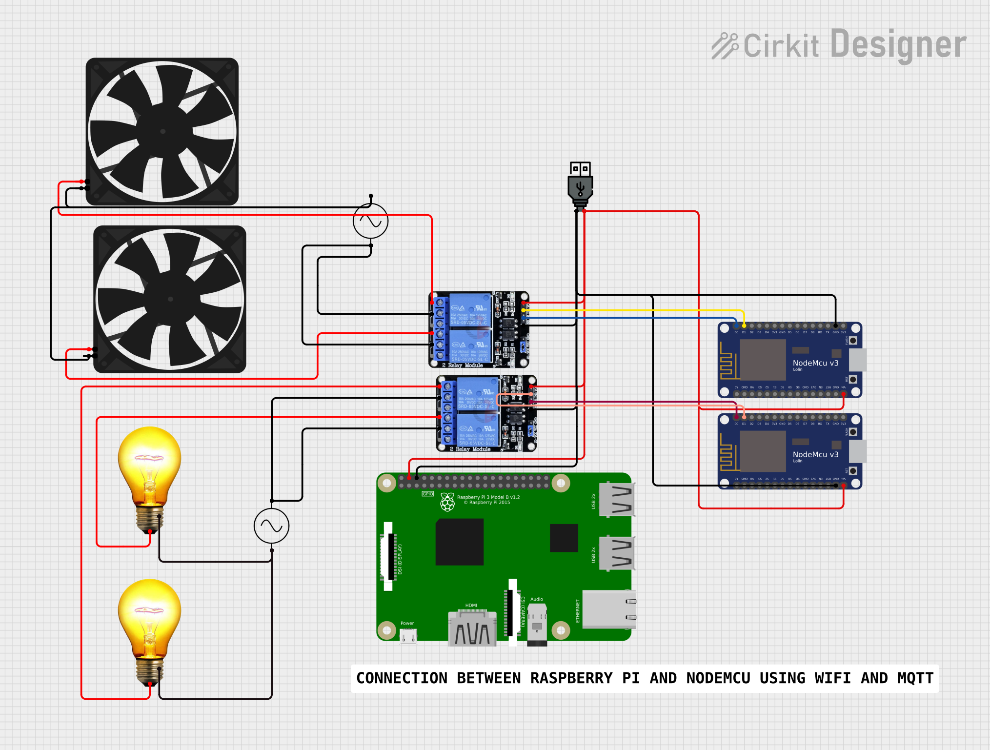
The circuit described in the provided inputs consists of a network of interconnected devices including two NodeMCU V3 ESP8266 microcontrollers, two 5V two-channel relays, a USB power source, two fans, two AC bulbs, two AC power supplies, and a Raspberry Pi 3B. The circuit appears to be designed for controlling AC-powered devices (bulbs and fans) using the relays, which are in turn controlled by the NodeMCU microcontrollers. The Raspberry Pi and NodeMCUs are powered by the USB power source. The AC power supplies are used to power the AC bulbs and fans through the relays.
Component List
NodeMCU V3 ESP8266
- Microcontroller with WiFi capability.
- Pins: A0, GND, VU, S3, S2, S1, SC, S0, SK, 3V3, EN, RST, Vin, D0, D1, D2, D3, D4, D5, D6, D7, D8, RX, TX.
Two Channel Relay 5v
- Relay module capable of controlling high power devices.
- Pins: VCC, IN2, IN1, GND, NC2, C2, NO2, NC1, C1, NO1.
USB Power
- Power source for the circuit.
- Pins: +, -.
Fan
- 5V DC fan for cooling purposes.
- Pins: GND, 5V.
AC Bulb
- Standard AC-powered light bulb.
- Pins: P, N.
AC Supply
- Provides AC power to the circuit.
- Pins: +ve, -ve.
Raspberry Pi 3B
- A small single-board computer.
- Pins: 3v3, GPIO2, GPIO3, GPIO4, GND, GPIO17, GPIO27, GPIO22, 3V3, GPIO10, GPIO9, GPIO11, ID_SD, GPIO5, GPIO6, GPIO13, GPIO19, GPIO26, GPIO21, GPIO20, GPIO16, GPIO12, ID_SC, GPIO7, GPIO8, GPIO25, GPIO24, GPIO23, GPIO18, GPIO15, GPIO14, 5V.
Wiring Details
NodeMCU V3 ESP8266
- Vin connected to USB power (+) and Raspberry Pi 3B (5V).
- GND connected to USB power (-), Raspberry Pi 3B (GND), and all relay modules (GND).
- D0 and D1 are used to control the IN1 and IN2 pins of the relay modules, respectively.
Two Channel Relay 5v
- VCC connected to USB power (+).
- IN1 and IN2 controlled by NodeMCU V3 ESP8266 (D0 and D1).
- GND connected to USB power (-).
- NC1 and NC2 connected to fans.
- C1 and C2 connected to AC supply (+ve).
USB Power
- (+) connected to NodeMCU V3 ESP8266 (Vin), Raspberry Pi 3B (5V), and relay modules (VCC).
- (-) connected to NodeMCU V3 ESP8266 (GND), Raspberry Pi 3B (GND), and relay modules (GND).
Fan
- 5V connected to relay module (NC1 or NC2).
- GND connected to AC supply (-ve).
AC Bulb
- P connected to relay module (NC1 or NC2).
- N connected to AC supply (-ve).
AC Supply
- +ve connected to relay modules (C1 and C2).
- -ve connected to AC bulbs (N) and fans (GND).
Raspberry Pi 3B
- 5V connected to USB power (+).
- GND connected to USB power (-).
Documented Code
No code was provided in the input. If code for the microcontrollers is available, it should be included here with appropriate comments to explain the functionality and logic implemented for controlling the relays and, by extension, the connected AC devices.
Please note that the above documentation is based on the provided inputs. For a complete and accurate circuit description, additional information such as the purpose of each part in the circuit, the expected behavior, and the actual code running on the microcontrollers would be necessary.