
Arduino UNO Based Smart Irrigation and Temperature Control System
View and Edit Project In Cirkit Designer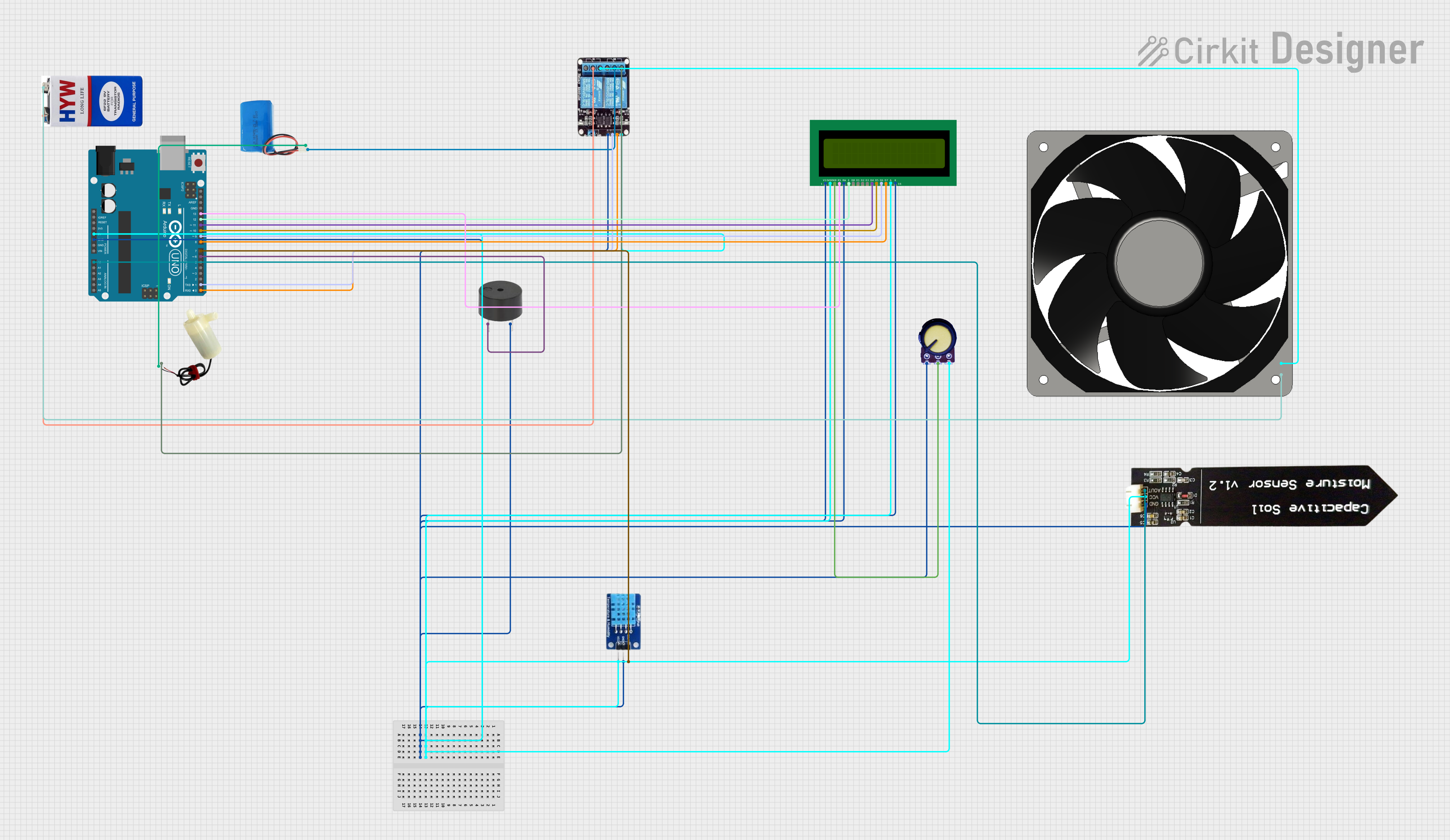
Smart Irrigation and Temperature Control System Documentation
Summary
This document describes a Smart Irrigation and Temperature Control System designed to automate the watering process of plants based on soil moisture levels and to control the temperature by activating a fan when needed. The system uses an Arduino UNO as the central processing unit, interfacing with various sensors and actuators including a DHT11 temperature and humidity sensor, a capacitive soil moisture sensor, a 16x2 LCD for display, a 2-channel relay module to control a water pump and a fan, and a buzzer for alerts. The system is powered by a 5V battery for the relay and sensors, and a 9V battery for the fan.
Component List
16X2 LCD
- Description: A liquid crystal display capable of displaying 16 characters per line across 2 lines.
- Purpose: To display temperature, humidity, and system status information.
2-Channel Relay
- Description: An electromechanical switch module with two channels, capable of controlling high power devices.
- Purpose: To switch the water pump and fan on and off based on sensor inputs.
5V Mini Water Pump
- Description: A small pump that operates at 5 volts for pumping water.
- Purpose: To irrigate plants when the soil moisture level is below the threshold.
DHT11
- Description: A basic, ultra-low-cost digital temperature and humidity sensor.
- Purpose: To measure air temperature and humidity for system decisions.
Arduino UNO
- Description: A microcontroller board based on the ATmega328P.
- Purpose: To control the system logic, read sensor data, and drive the LCD, relay, and buzzer.
Buzzer
- Description: An electronic sounder or beeper.
- Purpose: To provide audible alerts or feedback.
5V Battery
- Description: A power source providing 5 volts.
- Purpose: To power the relay module and the mini water pump.
9V Battery
- Description: A power source providing 9 volts.
- Purpose: To power the 12V fan through the relay module.
120mm Fan 12V
- Description: A 120mm fan that operates at 12 volts for cooling.
- Purpose: To cool down the environment when the temperature exceeds the threshold.
Capacitive Soil Moisture Sensor V1.2
- Description: A sensor that measures the moisture level in the soil.
- Purpose: To monitor soil moisture levels for irrigation control.
Potentiometer
- Description: A three-terminal resistor with a rotating contact that forms an adjustable voltage divider.
- Purpose: To adjust the contrast of the LCD display.
Wiring Details
16X2 LCD
- VDD: Connected to 5V power supply.
- VSS: Connected to ground.
- V0: Connected to the output of the potentiometer for contrast adjustment.
- RS: Connected to digital pin D13 of the Arduino UNO.
- RW: Connected to ground.
- E: Connected to digital pin D12 of the Arduino UNO.
- D4-D7: Connected to digital pins D11-D8 of the Arduino UNO, respectively.
- A: Connected to 5V power supply (backlight anode).
- K: Connected to ground (backlight cathode).
2-Channel Relay
- VCC: Connected to 5V power supply.
- GND: Connected to ground.
- IN1: Connected to digital pin D1 of the Arduino UNO.
- IN2: Connected to digital pin D0 of the Arduino UNO.
- COM: Connected to the positive terminal of the 9V battery.
- NO: Connected to the positive pin of the 120mm fan 12V and the positive pin of the 5V mini water pump.
5V Mini Water Pump
- Positive Pin: Connected to the NO terminal of the 2-channel relay.
- Negative Pin: Connected to the negative terminal of the 5V battery.
DHT11
- VCC: Connected to 5V power supply.
- GND: Connected to ground.
- DATA: Connected to digital pin D7 of the Arduino UNO.
Arduino UNO
- 5V: Connected to the 5V power supply rail.
- GND: Connected to the ground rail.
- Digital Pins D0-D13: Connected to various components as per the control logic.
- Analog Pin A0: Connected to the AOUT pin of the capacitive soil moisture sensor.
Buzzer
- PIN: Connected to digital pin D6 of the Arduino UNO.
- GND: Connected to ground.
Capacitive Soil Moisture Sensor V1.2
- VCC: Connected to 5V power supply.
- GND: Connected to ground.
- AOUT: Connected to analog pin A0 of the Arduino UNO.
Potentiometer
- VCC: Connected to 5V power supply.
- GND: Connected to ground.
- Output: Connected to V0 pin of the 16X2 LCD.
Documented Code
#include <DHT.h>
#include <LiquidCrystal.h>

// Definition of pins for sensors and relays
#define DHTPIN 7       // Pin for the DHT11 sensor
#define DHTTYPE DHT11  // Type of sensor used
#define FAN_PIN 1      // Pin for fan control
#define RELAY_PIN 0    // Pin for relay control (pump)
#define MOISTURE_SENSOR_PIN A0  // Analog pin for soil moisture sensor

// Thresholds
const int moistureThreshold = 500; // Threshold for soil moisture
const float tempThreshold = 35.0;  // Temperature threshold for activating the fan

// Initialization of objects
DHT dht(DHTPIN, DHTTYPE);
LiquidCrystal lcd(13, 12, 11, 10, 9, 8);

void setup() {
  // Initialize pins
  pinMode(FAN_PIN, OUTPUT);
  pinMode(RELAY_PIN, OUTPUT);
  pinMode(MOISTURE_SENSOR_PIN, INPUT);

  // Initialize serial monitor and LCD
  Serial.begin(9600);
  lcd.begin(16, 2);

  // Startup message
  Serial.println("Smart Irrigation and Temperature Control System");
  lcd.print("System Starting");
  delay(2000); // Wait for 2 seconds
  lcd.clear();

  // Initialize DHT sensor
  dht.begin();
}

void loop() {
  // Read soil moisture
  int moistureValue = analogRead(MOISTURE_SENSOR_PIN);

  // Read air humidity and temperature
  float humidity = dht.readHumidity();
  float temperature = dht.readTemperature();

  // Check if sensor readings failed
  if (isnan(humidity) || isnan(temperature)) {
    Serial.println("Failed to read from DHT sensor!");
    return;
  }

  // Control the pump based on soil moisture
  if (moistureValue < moistureThreshold) {
    digitalWrite(RELAY_PIN, HIGH);  // Turn on the pump
    lcd.setCursor(0, 1);
    lcd.print("Irrigating    ");
  } else {
    digitalWrite(RELAY_PIN, LOW);   // Turn off the pump
    lcd.setCursor(0, 1);
    lcd.print("Pump off     ");
  }

  // Control the fan based on temperature
  if (temperature > tempThreshold) {
    digitalWrite(FAN_PIN, HIGH);    // Turn on the fan
  } else {
    digitalWrite(FAN_PIN, LOW);     // Turn off the fan
  }

  // Display results on the LCD
  lcd.setCursor(0, 0);
  lcd.print("Temp: ");
  lcd.print(temperature);
  lcd.print("C  ");
  lcd.setCursor(10, 0);
  lcd.print("H: ");
  lcd.print(humidity);
  lcd.print("%  ");

  // Print soil moisture to the serial monitor
  Serial.print("Soil Moisture: ");
  Serial.print(moistureValue);
  Serial.print(" | Temp: ");
  Serial.print(temperature);
  Serial.print(" C | Humidity: ");
  Serial.print(humidity);
  Serial.println(" %");

  // Pause before the next reading
  delay(2000);
}
This code is responsible for reading the soil moisture and air temperature and humidity, controlling the water pump and fan based on predefined thresholds, and displaying the status and sensor readings on the LCD and serial monitor.