ESP8266-Based Environmental Monitoring System with GPS, GSM, and Sensor Integration
Circuit Documentation
Summary
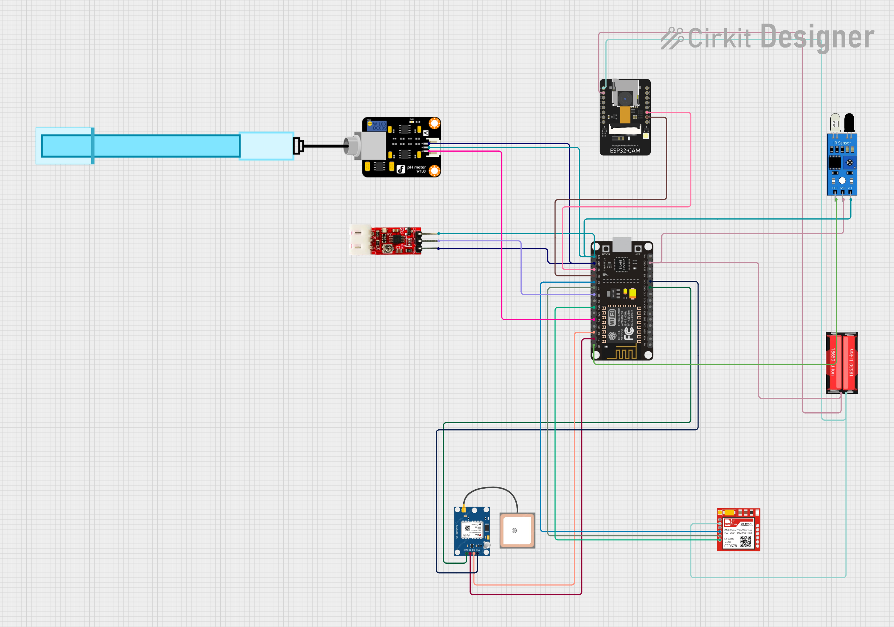
This document provides a detailed overview of a circuit designed to interface various sensors and modules with an ESP8266 NodeMCU microcontroller. The circuit includes an IR sensor, a GPS module (NEO 6M), a turbidity sensor, a pH meter, a SIM800L GSM module, an ESP32-CAM module, and a power source in the form of an 18650 Li-Ion battery. The ESP8266 NodeMCU serves as the central processing unit, handling sensor data and communication with the GPS and GSM modules, as well as interfacing with the ESP32-CAM.
Component List
IR Sensor
- Pins: out, gnd, vcc
- Description: An infrared sensor used for detecting obstacles or measuring distances.
18650 Li-Ion Battery
- Pins: Positive, Negative
- Description: A rechargeable lithium-ion battery providing power to the circuit.
GPS NEO 6M Module
- Pins: VCC, RX, TX, GND
- Description: A GPS module for obtaining geographical location data.
PH Meter
- Pins: Signal, VCC, GND
- Description: A sensor for measuring the pH level of a solution.
Sim800l GSM Module
- Pins: NET, RST, VCC, RXD, TXD, GND
- Description: A GSM module for cellular communication.
ESP8266 NodeMCU
- Pins: D0-D8, RX, TX, A0, 3V3, GND, RSV, SD0-SD3, CMD, CLK, EN, RST, VIN
- Description: A Wi-Fi enabled microcontroller for managing the sensors and communication modules.
ESP32-CAM
- Pins: 5V, GND, IO0-IO16, 3V3, VOT, VOR, VCC
- Description: A camera module with Wi-Fi capabilities.
Turbidity Module
- Pins: VCC, GND, OUT
- Description: A sensor for measuring the turbidity (cloudiness) of a liquid.
Wiring Details
IR Sensor
- out connected to ESP8266 NodeMCU D0
- gnd connected to common ground
- vcc connected to ESP8266 NodeMCU 3V3
18650 Li-Ion Battery
- Positive connected to ESP32-CAM 5V and Sim800l VCC
- Negative connected to common ground
GPS NEO 6M Module
- VCC connected to ESP8266 NodeMCU 3V3
- RX connected to ESP8266 NodeMCU D2
- TX connected to ESP8266 NodeMCU D1
- GND connected to common ground
PH Meter
- Signal connected to ESP8266 NodeMCU D4
- VCC connected to ESP8266 NodeMCU 3V3
- GND connected to common ground
Sim800l GSM Module
- NET (not connected)
- RST (not connected)
- VCC connected to 18650 Li-Ion Battery Positive
- RXD connected to ESP8266 NodeMCU D8
- TXD connected to ESP8266 NodeMCU D7
- GND connected to common ground
ESP8266 NodeMCU
- 3V3 connected to IR Sensor vcc, Turbidity Module VCC, PH Meter VCC, and GPS NEO 6M VCC
- GND connected to common ground
- D0 connected to IR Sensor out
- D1 connected to GPS NEO 6M TX
- D2 connected to GPS NEO 6M RX
- D4 connected to PH Meter Signal
- D6 connected to Turbidity Module OUT
- D7 connected to Sim800l TXD
- D8 connected to Sim800l RXD
- RX connected to ESP32-CAM VOT
- TX connected to ESP32-CAM VOR
ESP32-CAM
- 5V connected to 18650 Li-Ion Battery Positive
- GND connected to common ground
- VOT connected to ESP8266 NodeMCU RX
- VOR connected to ESP8266 NodeMCU TX
Turbidity Module
- VCC connected to ESP8266 NodeMCU 3V3
- GND connected to common ground
- OUT connected to ESP8266 NodeMCU D6
Documented Code
ESP8266 NodeMCU Code (sketch.ino)
void setup() {
  // put your setup code here, to run once:

}

void loop() {
  // put your main code here, to run repeatedly:

}
This code is a template for the ESP8266 NodeMCU microcontroller. The setup() function is called once when the microcontroller is powered on or reset. It is used to initialize the pins and set up the communication protocols. The loop() function is called repeatedly and contains the main logic of the program. It is where the microcontroller reads sensor data, processes it, and performs actions such as sending data over Wi-Fi or GSM.