
Arduino Nano-Controlled Time-Tracking Device with Stepper Motor and OLED Display
View and Edit Project In Cirkit Designer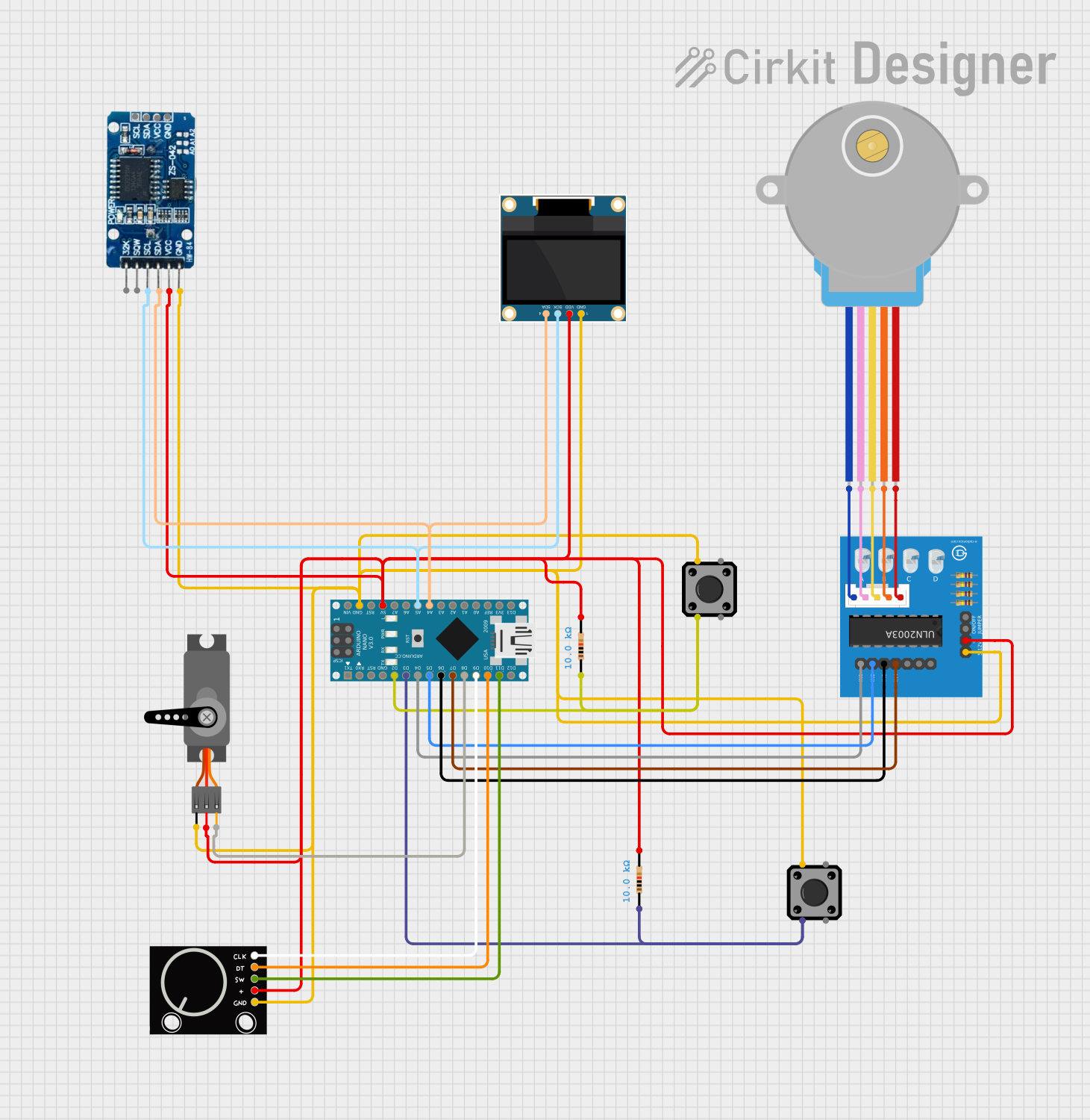
Circuit Documentation
Summary
This document provides a detailed overview of a circuit that includes an Arduino Nano as the central microcontroller, interfaced with various components such as a stepper motor, servo motor, rotary encoder, resistors, tactile switches, an OLED display, and an RTC module. The circuit is designed to perform multiple functions, which could include user input through switches and a rotary encoder, visual feedback through an OLED display, timekeeping with an RTC module, and motion control with a stepper and servo motor.
Component List
Arduino Nano
- Microcontroller board based on the ATmega328P
- Pins: D1/TX, D0/RX, RESET, GND, D2-D13, VIN, 5V, A0-A7, AREF, 3V3
Resistor (10k Ohms)
- Passive two-terminal electrical component used to limit current
- Resistance: 10,000 Ohms
Tactile Switch Buttons - 12mm Square
- Simple switch mechanism for user input
- Pins: 1, 2, 3, 4
28BYJ-48 Stepper Motor
- Small, 5-wire, unipolar stepper motor
- Pins: BLUE, PINK, YELLOW, ORANGE, RED
ULN2003A Breakout Board
- Darlington transistor array for driving high-current loads
- Pins: In 1-7, 0V, +5V, ON/OFF jumper switch, BLUE wire, PINK wire, YELLOW wire, ORANGE wire, RED wire
RTC DS3231
- Real-Time Clock module for timekeeping
- Pins: 32K, SQW, SCL, SDA, VCC, GND
0.96" OLED
- Small display for visual output
- Pins: GND, VDD, SCK, SDA
Servo
- Motor capable of precise angular positioning
- Pins: GND, VCC, PWM
Rotary Encoder
- Input device that provides rotational position feedback
- Pins: GND, +, SW, DT, CLK
Wiring Details
Arduino Nano
- D2 connected to Resistor (10k Ohms) and Tactile Switch
- D3 connected to Resistor (10k Ohms) and Tactile Switch
- D4-D7 connected to ULN2003A Breakout Board (In 1-4)
- D8 connected to Servo (PWM)
- D9 connected to Rotary Encoder (CLK)
- D10 connected to Rotary Encoder (DT)
- D11/MOSI connected to Rotary Encoder (SW)
- GND connected to common ground net
- 5V connected to common power net
- A4 (SDA) connected to RTC DS3231 (SDA) and 0.96" OLED (SDA)
- A5 (SCL) connected to RTC DS3231 (SCL) and 0.96" OLED (SCK)
Resistor (10k Ohms)
- One pin connected to Arduino Nano (D2, D3)
- Other pin connected to Tactile Switch and common power net
Tactile Switch Buttons - 12mm Square
- Pin 3 connected to Arduino Nano (D2, D3) through Resistor (10k Ohms)
- Pin 1 connected to common ground net
28BYJ-48 Stepper Motor
- Pins BLUE, PINK, YELLOW, ORANGE, RED connected to corresponding wires on ULN2003A Breakout Board
ULN2003A Breakout Board
- In 1-4 connected to Arduino Nano (D4-D7)
- 0V connected to common ground net
- +5V connected to common power net
- BLUE, PINK, YELLOW, ORANGE, RED wires connected to corresponding pins on 28BYJ-48 Stepper Motor
RTC DS3231
- SCL connected to Arduino Nano (A5) and 0.96" OLED (SCK)
- SDA connected to Arduino Nano (A4) and 0.96" OLED (SDA)
- VCC connected to common power net
- GND connected to common ground net
0.96" OLED
- SCK connected to Arduino Nano (A5) and RTC DS3231 (SCL)
- SDA connected to Arduino Nano (A4) and RTC DS3231 (SDA)
- VDD connected to common power net
- GND connected to common ground net
Servo
- PWM connected to Arduino Nano (D8)
- VCC connected to common power net
- GND connected to common ground net
Rotary Encoder
- CLK connected to Arduino Nano (D9)
- DT connected to Arduino Nano (D10)
- SW connected to Arduino Nano (D11/MOSI)
-
- connected to common power net
- GND connected to common ground net
Documented Code
Arduino Nano - sketch.ino
void setup() {
  // put your setup code here, to run once:

}

void loop() {
  // put your main code here, to run repeatedly:

}
Arduino Nano - documentation.txt
(No additional documentation provided for the code)